Cable tray bend: how to make vertical and horizontal 90 and 45 degree bends with a V notch
Updated on 06 November 2026
A factory cable tray bend is a catalogue fitting, but on site it is usually made from the tray itself: cut a V notch, bend until the V closes, and splice. This guide gives the notch for the vertical and the horizontal bend, at 90 and at 45 degrees, and the open curve made of several notches, with a full-size template to wrap round the tray and mark the cut.
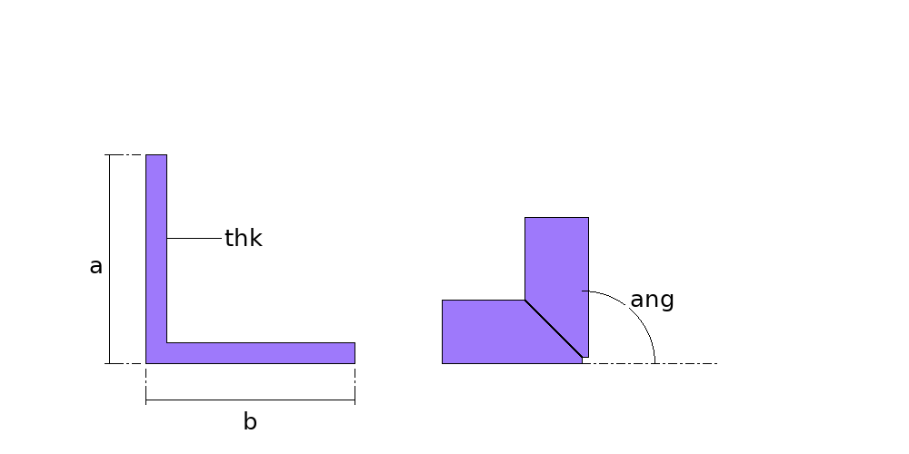
The arithmetic is the Angle Iron V-Notch Bend calculator, which covers the channel standing up (the vertical bend) and lying on its side (the horizontal bend). The examples below open already worked out.
Vertical bend and horizontal bend
In a VERTICAL bend the tray turns towards its side rails: with the tray open side up, it is the bend that rises. The bottom stays on the outside of the bend and is not cut -- it is the hinge -- and each side rail gets a V that closes as you bend. In the calculator this is "Channel upright (V in both flanges)".
In a HORIZONTAL bend the tray turns sideways, in the plane of its bottom. The V crosses the bottom, the inner side rail gets a slot as wide as the mouth of the V, and the outer side rail is the hinge. In the calculator this is "Channel on its side (V in the web)".
A bend towards the bottom, with the tray open side up, cannot be made with a V: the only metal on its outside would be the edges of the side rails, with nothing whole to act as a hinge. It is made with a splice plate or with a factory fitting.
The size of the cut
- Vertical bend: the V in each side rail
opening = 2 × (a − t) × tan(α / 2)a is the side rail height, outside, t the thickness and α the bend angle. The V runs down to the hinge line, one thickness from the outside face of the bottom. On a 100 × 50 mm tray in 1.5 mm sheet the V opens 97 mm at the edge at 90°, and 40.2 mm at 45°.
- Horizontal bend: the V in the bottom and the slot in the inner rail
slot = 2 × (b − t) × tan(α / 2)b is the bottom width, outside. On the same tray the slot is 197 mm at 90° and 81.6 mm at 45°: the horizontal bend removes far more metal, because the cut crosses the whole width of the bottom.
- Open curve, in several notches
α = angle / n ; pitch = 2 × (R − t) × sin(α / 2)R is the bend radius on the outside face of the part that bends. A vertical 90° bend at 400 mm radius in 6 notches has 15° Vs opening 12.8 mm, 104 mm apart, leaving 91.3 mm of rail between two. A horizontal 90° bend at 600 mm radius in 6 notches has 25.9 mm slots every 156.2 mm.
Worked examples
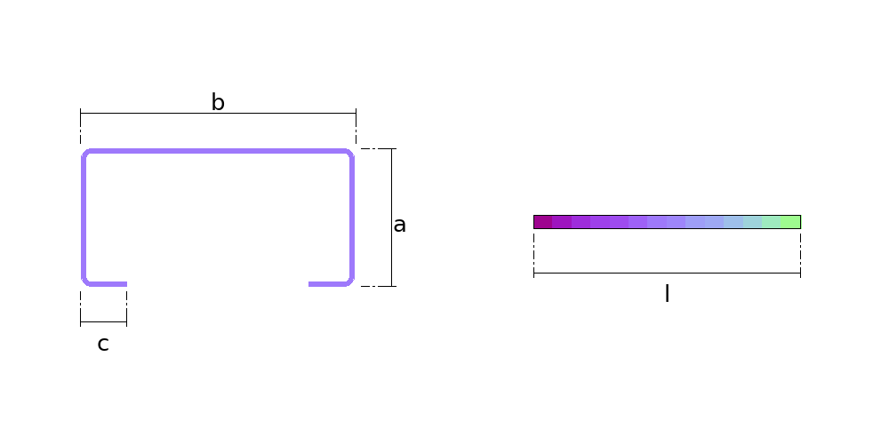
A 100 × 50 mm tray in 1.5 mm sheet with a 3 mm outside corner radius. Each row opens the part with the measurements, the 1:1 template and the DXF.
| Bend | The cut | Template | |
|---|---|---|---|
| Vertical 90° | 97 mm V in each rail | 197 × 157 mm | open |
| Vertical 45° | 40.2 mm V in each rail | 197 × 100 mm | open |
| Vertical 90°, 400 radius, 6 notches | 12.8 mm V every 104 mm | 593 × 197 mm | open |
| Horizontal 90° | V in the bottom, 197 mm slot | 257 × 197 mm | open |
| Horizontal 45° | V in the bottom, 81.6 mm slot | 197 × 142 mm | open |
| Horizontal 90°, 600 radius, 6 notches | 25.9 mm slot every 156 mm | 867 × 197 mm | open |
How to cut and bend
- Work it out with the side rail height and the bottom width outside, the thickness, the corner radius and the bend angle; for an open curve, the number of notches and the radius.
- Print the template at full size, cut it out and wrap it round the outside of the tray, with the straight edges square and the long dashed lines on the corners.
- Mark each V, the slot of a horizontal bend and the bend line, one thickness from the outside face of the part that bends.
- Cut with a thin disc down to the hinge line without cutting the part that bends, and deburr the edges: cable pulled over a sharp edge cuts its insulation.
- Bend slowly until the faces of the V meet. On galvanized tray, close it with rivets or bolts and a splice plate inside instead of welding, which burns off the zinc.
Common mistakes
- Cutting the hinge. The bottom, in a vertical bend, and the outer rail, in a horizontal one, stay whole: cut through, the tray comes apart.
- Slotting the wrong rail in a horizontal bend. The slot goes in the INNER rail, the one that shortens; in the outer rail the bend opens the cut instead of closing it.
- Notches too close on an open curve. If two Vs touch at the edge, no rail is left between them and the curve does not hold. The calculation refuses less than one thickness between notches: increase the radius or use fewer notches.
- Measuring the tray inside. The formula takes the outside sizes, the ones in the manufacturer's catalogue.
Frequently asked questions
- How do you make a 90 degree bend in cable tray?
- For a vertical bend, cut a V in each side rail down to the hinge line, one thickness from the bottom, and bend until the V closes. The V opens 2 × (a − t) × tan 45° at the rail edge: 97 mm on a 100 × 50 mm tray in 1.5 mm sheet. For a horizontal bend the V goes in the bottom and the inner rail gets a 2 × (b − t) slot: 197 mm on the same tray.
- How do you make a horizontal bend in cable tray?
- Cut a V through the whole width of the bottom and open a slot as wide as the mouth of the V in the inner side rail; the outer rail stays whole and bends. At 45° the slot on a 100 × 50 mm tray in 1.5 mm sheet is 81.6 mm.
- How do you make a large-radius cable tray bend?
- In several small notches: divide the angle by the number of notches and space them 2 × (R − t) × sin(α/2) apart. A vertical 90° bend at 400 mm radius in 6 notches has 12.8 mm Vs every 104 mm. More notches make a smoother curve, as long as some rail is left between them.
- Can I bend perforated cable tray this way?
- Yes, with the same template. Just check that the bend line does not fall on a hole, which weakens the hinge: if it does, move the bend half a hole pitch.
Parts in this guide
Other guides
- How to develop a cone (frustum) in sheet metal: formula, sector radii and angle, step by step
- Lobster back bend calculator (segmented 90° elbow): gore angles, cut heights and how many plates
- Pipe saddle calculator and development: how to lay out a pipe-to-pipe branch (tee) at 90 and 45 degrees
- Square to round transition: development by triangulation, step by step
- Bend allowance and K-factor calculator, and the neutral axis: why every development uses D − t
- Sheet metal glossary: the terms of marking out and pattern development in plate fabrication
- How we check the Planichapa calculations, and who is behind them
- Plate 'n' Sheet alternative: Planichapa develops sheet metal parts in the browser, with the price on the page
- LITIO alternative: Planichapa develops sheet metal parts in the browser, nothing to install, now that LITIO2 is no longer sold
- How to lay out a mitre-cut pipe: paper template, sine wave and ordinate table
- Steel plate weight calculator, weight per m², gauges and stock plate sizes: table and formula
- Pipe ovality: a calculator, the formula, a worked example, the limits the codes use and how to measure it in the shop
- Sheet metal pattern development software: how to choose, and what changes between a desktop program, a phone app and an online calculator
- Eccentric and concentric reducers: which one to use and how each one develops on plate
- Roller chain size chart: ANSI, ISO 606, motorcycle and bicycle chain pitch and roller diameter
- Sprocket dimensions: pitch diameter, outside and root diameter, tooth form and a pitch diameter chart
- Bolt circle layout: the position of each hole, the chord between holes and a chord chart
- Chain length and sprocket ratio: the formulas, a worked example and how many links to cut
- Screw flight calculator: the flat blank of a screw conveyor flight (auger), with the formula and a worked example
- Plate rolling calculator: the blank length of a rolled shell, with the formula, a chart and a worked example
- Tube notching template generator: a printable coping template for any tube, angle and offset
- Dished head calculator: depth, volume, blank diameter and weight of torispherical, 2:1 elliptical and hemispherical heads
- Cone template generator: a printable full-size cone template for hoppers, funnels and reducers
- Pie cut calculator for exhaust and tube bends: saw angle, pie lengths and a wrap-around template
- Duct transition layout: square to round duct, centred, offset or flat on one side
- Pipe template, printable at full size: tee saddle, 45° lateral and mitre cut for every pipe size from NPS 1/2 to 12
- Register boot layout: from a floor, wall or ceiling register to a round duct, in inches
- Plenum box and plenum transition layout: the sides, the end cap, the collar and the transitions
- Smoker stack and firebox templates: the cuts where pipe meets the cook chamber, in inches
- Laser and plasma cutting cost calculator: the formula, a worked example and how to measure the cut length
- Tank volume calculator and strapping chart: horizontal and vertical tanks with 2:1, torispherical, hemispherical or flat heads
- Merge collector template generator: a printable cutting template for 2, 3, 4, 6 or 8 into 1
- Dome template generator: printable gores for a dome or a hemisphere in paper, EVA foam or sheet metal
- DIY cyclone dust collector plans: every sheet of the cyclone from the Stairmand proportions, for any duct size