Bolt circle layout: the position of each hole, the chord between holes and a chord chart
Updated on 21 October 2026
A bolt circle -- the pitch circle diameter, PCD, of the holes -- comes down to one number per hole: its angle. From the angle come the coordinates for the drill or the CNC, and the chord between neighbouring holes, which is how the circle is stepped out with dividers when there is no protractor. This guide gives the three formulas, a worked example, a chord chart for 3 to 24 holes and the rule the flange standards follow for where the first hole goes.
The flange calculator does it for any drilling, draws the holes and fills in the ASME B16.5 and EN 1092-1 drillings with one click.
The formulas
- Angle between holes
β = 360° / nn is the number of holes. Eight holes: 45°.
- Position of each hole
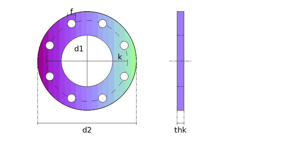
θi = θ0 + i × β ; xi = (K / 2) × cos θi ; yi = (K / 2) × sin θiK is the bolt circle diameter and θ0 the angle of the first hole. Flange standards put θ0 at half a pitch, β / 2, so that no hole sits on a centre line.
- Chord between neighbouring holes
c = K × sin(180° / n)The straight distance between two neighbouring hole centres, which is the divider setting.
Worked example: a DN 100 PN 16 flange
EN 1092-1, DN 100, PN 16: 8 holes of 18 mm on a 180 mm bolt circle. The angle between holes is 45°, and the first hole sits at 22.5°.
| Hole | Angle | x (mm) | y (mm) |
|---|---|---|---|
| 1 | 22.5° | 83.15 | 34.44 |
| 2 | 67.5° | 34.44 | 83.15 |
| 3 | 112.5° | -34.44 | 83.15 |
| 4 | 157.5° | -83.15 | 34.44 |
| 5 | 202.5° | -83.15 | -34.44 |
| 6 | 247.5° | -34.44 | -83.15 |
| 7 | 292.5° | 34.44 | -83.15 |
| 8 | 337.5° | 83.15 | -34.44 |
The chord is 180 × sin 22.5° = 68.88 mm: set the dividers to it, start at the first hole and step round the circle; the eighth step must land back on the first hole.
Bolt circle chord chart
The chord is the bolt circle diameter times a factor that depends only on the number of holes, sin(180° / n). Multiply the factor by your bolt circle, or read the 100 mm and 4 in columns.
| Holes | Angle between holes | Chord factor | Chord, 100 mm circle (mm) | Chord, 4 in circle (in) |
|---|---|---|---|---|
| 3 | 120° | 0.8660 | 86.60 | 3.464 |
| 4 | 90° | 0.7071 | 70.71 | 2.828 |
| 5 | 72° | 0.5878 | 58.78 | 2.351 |
| 6 | 60° | 0.5000 | 50.00 | 2.000 |
| 7 | 51.43° | 0.4339 | 43.39 | 1.736 |
| 8 | 45° | 0.3827 | 38.27 | 1.531 |
| 9 | 40° | 0.3420 | 34.20 | 1.368 |
| 10 | 36° | 0.3090 | 30.90 | 1.236 |
| 12 | 30° | 0.2588 | 25.88 | 1.035 |
| 16 | 22.5° | 0.1951 | 19.51 | 0.780 |
| 20 | 18° | 0.1564 | 15.64 | 0.626 |
| 24 | 15° | 0.1305 | 13.05 | 0.522 |
Where the first hole goes
ASME B16.5, EN 1092-1 and the other flange standards straddle the centre lines: the first hole half a pitch off the vertical, so that the flange mates with its counterpart in any symmetric position and no bolt sits at the lowest point, where water collects. On 4 holes that is 45° from the centre line; on 8 holes, 22.5°.
Marking out by hand
- Scribe the bolt circle from the centre punch, with a trammel or dividers set to half the bolt circle diameter.
- Mark the first hole half a pitch from the centre line, by protractor or by its coordinates.
- Set the dividers to the chord and step round the circle. The last step must close on the first hole; if it overshoots or falls short, correct the setting and start again.
- Centre-punch every hole and drill a pilot before the full size.
Common mistakes
- A hole on a centre line: the flange then sits half a pitch rotated from its counterpart, and the valve or the pump goes in crooked.
- Using the radius where the formula wants the diameter: the chord is K × sin(180° / n), with K the bolt circle diameter.
- Stepping the chord on the wrong circle: the dividers go round the bolt circle, not round the outside of the flange.
Frequently asked questions
- How do you calculate a bolt circle?
- Divide 360° by the number of holes for the angle between them, put the first hole half a pitch off the centre line, and take each hole at x = (K / 2) × cos θ and y = (K / 2) × sin θ, with K the bolt circle diameter.
- What is the distance between bolt holes on a bolt circle?
- The chord, K × sin(180° / n). On a 180 mm circle with 8 holes it is 68.88 mm.
- What does PCD mean?
- Pitch circle diameter: the diameter of the circle through the hole centres, the same thing as the bolt circle. EN 1092-1 calls it K.
Parts in this guide
Other guides
- How to develop a cone (frustum) in sheet metal: formula, sector radii and angle, step by step
- Lobster back bend calculator (segmented 90° elbow): gore angles, cut heights and how many plates
- Pipe saddle calculator and development: how to lay out a pipe-to-pipe branch (tee) at 90 and 45 degrees
- Square to round transition: development by triangulation, step by step
- The neutral axis of plate: why every development uses D − t, and the bend deduction
- Sheet metal glossary: the terms of marking out and pattern development in plate fabrication
- How we check the Planichapa calculations, and who is behind them
- LITIO alternative: Planichapa develops sheet metal parts in the browser, nothing to install, now that LITIO2 is no longer sold
- How to lay out a mitre-cut pipe: paper template, sine wave and ordinate table
- Plate 'n' Sheet alternative: Planichapa develops sheet metal parts in the browser, with the price on the page
- Steel plate weight calculator, weight per m², gauges and stock plate sizes: table and formula
- Pipe ovality: a calculator, the formula, a worked example, the limits the codes use and how to measure it in the shop
- Sheet metal pattern development software: how to choose, and what changes between a desktop program, a phone app and an online calculator
- Eccentric and concentric reducers: which one to use and how each one develops on plate
- Roller chain size chart: ANSI, ISO 606, motorcycle and bicycle chain pitch and roller diameter
- Sprocket dimensions: pitch diameter, outside and root diameter, tooth form and a pitch diameter chart
- Chain length and sprocket ratio: the formulas, a worked example and how many links to cut
- Screw flight calculator: the flat blank of a screw conveyor flight (auger), with the formula and a worked example
- Plate rolling calculator: the blank length of a rolled shell, with the formula, a chart and a worked example
- Tube notching template generator: a printable coping template for any tube, angle and offset
- Dished head calculator: depth, volume, blank diameter and weight of torispherical, 2:1 elliptical and hemispherical heads
- Cone template generator: a printable full-size cone template for hoppers, funnels and reducers
- Pie cut calculator for exhaust and tube bends: saw angle, pie lengths and a wrap-around template
- Duct transition layout: square to round duct, centred, offset or flat on one side
- Pipe template, printable at full size: tee saddle, 45° lateral and mitre cut for every pipe size from NPS 1/2 to 12
- Register boot layout: from a floor, wall or ceiling register to a round duct, in inches
- Plenum box and plenum transition layout: the sides, the offset and the round outlet