How we check the Planichapa calculations, and who is behind them
Updated on 15 September 2026
A tidy drawing on screen does not prove the pattern is right. The arithmetic of an impossible triangle still produces a plausible vertex; a plate that develops half the part closes its outline and exports a clean DXF. This page says who makes Planichapa, what is checked on every part before it enters the catalogue, and the mistakes that have already been found and fixed, because owning up to a corrected error is worth more to anyone who works with plate than any promise.
Who makes it
Planichapa is operated by FOOLABS, Brazilian company number (CNPJ) 37.724.297/0001-48, in Joinville, Santa Catarina, the metalworking hub of southern Brazil. The calculation of every part is open to inspection by anyone who uses it: the geometry of each of the 50 parts is written as a formula, the same one these pages show. Contact is through the form or the WhatsApp number in the footer, and a wrong result is fixed as a priority: that is what the terms of use promise.
The five checks on every part
Every part goes through automated tests that run on every change to the code. None of them looks at the drawing; all of them look at the geometry.
1. Every triangle is constructible
On triangulated parts, every declared triangle must satisfy a + b ≥ c. An impossible triangle does not fail the arithmetic on its own: the square root of a negative number becomes, in absolute value, a vertex that looks fine. The test rejects the triangle before it becomes a drawing.
2. The weld error is zero
Every vertex placed on the plate must sit at exactly the two distances its triangle was defined with. If the triangulation slipped anywhere, the seam does not close, and the test measures that in thousandths of a millimetre.
3. The plate area is the part area
The area of the flat pattern, adding every plate by its quantity, must be within about one per cent of the surface area of the 3D solid, computed independently from the mesh. It is the check that catches a missing piece: the square to round once shipped developing 0.4995 of its own surface, half the part in one plate marked as quantity one, and every other test passed. The inclined square to round, when it was revived, developed 38% of its own surface and looked perfectly reasonable on screen.
4. Figures published by third parties
Checking a part against itself proves consistency, not that the convention is the shop's. So each of the 50 parts is run with the inputs of an example published by someone else, and the output compared: the frustum against a worked example from layout literature, the segmented bend against the published mitre formula for piping, the screw flight against the flight formula of the screw-conveyor literature, the transitions against the surface development lecture of IIT Guwahati (ME 111, lecture 14). Where the source gives no thickness, the test uses a thousandth of a millimetre, and what remains is the pure geometry the source published.
5. The neutral axis on every part
Forty-nine of the fifty parts develop on the neutral axis, at mid-thickness, and a test checks each against the formula: π × (D − t) on the shell and on every gore, (t/2) × cos α on the cone. The fiftieth is the spherical head, which is not developable: its template is the shop layout, exact in area, and the part page says so in plain words.
And the 3D mesh
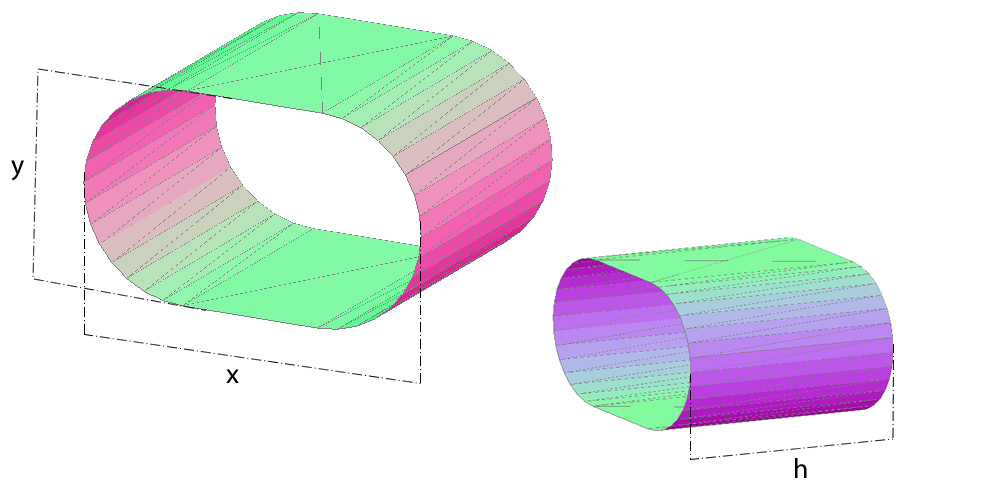
The 3D model of each part, the one the page shows, passes two mesh checks: no edge in more than two faces, and no zero-area face. That is how the oval tube was found to have an edge a slicer reads as non-manifold.
Mistakes we have found and fixed
The list is in the code history, dated. The ones that changed a figure someone could have cut:
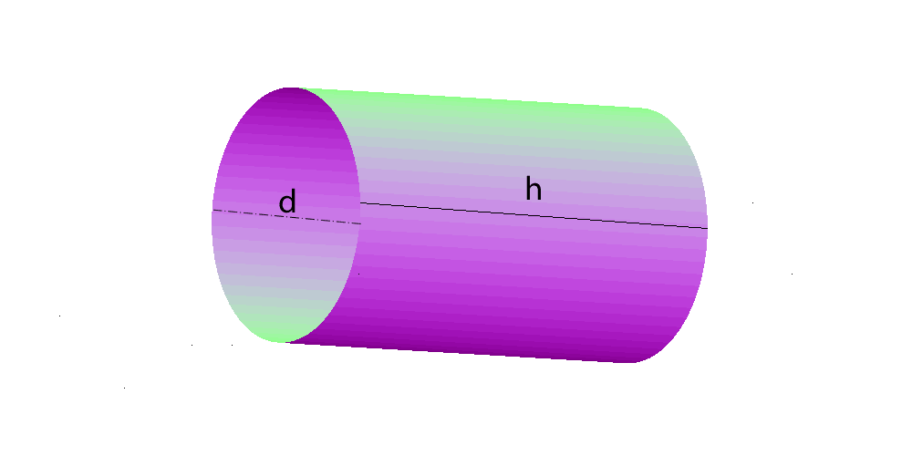
- Cylinder with π × D. The shell came out π × t long: 9.4 mm on 300 × 3, 31 mm on 800 × 10, and the seam overlapped. Fixed to π × (D − t), and the neutral-axis test was born from it.
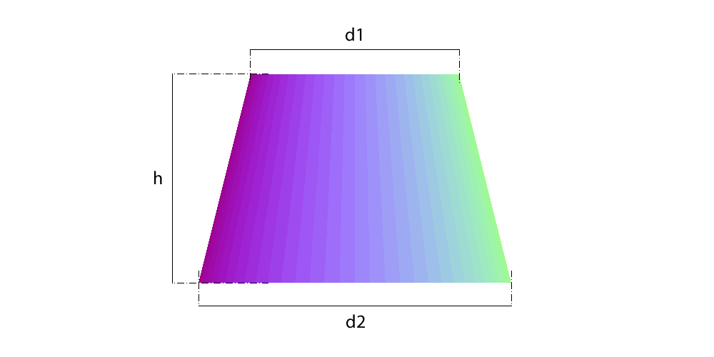
- Cone with t/2 off the radius (1 September 2026). The correct offset is normal to the surface, (t/2) × cos α. On a thin-wall reducer the difference is a tenth of a millimetre; on an 800 by 60 conical cap in 20 mm plate it was over 50 mm of arc. The proof is the limit: a flat washer takes no offset.
- Oval tube k-factor (1 September 2026). The perimeter of the flat-oval section used a wrong factor on the straight runs; checked against an outside figure and fixed, along with the sweep of all 50 parts.
- Elliptical tube developed on the reduced-axis ellipse (1 September 2026). The mean-surface perimeter of an ellipse is that of the parallel curve, not of another ellipse with the axes shortened by t. Fixed.
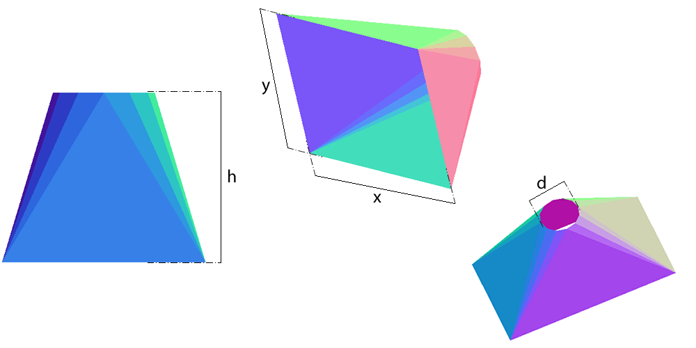
- Square to round with half the plate. The part developed 0.4995 of its own surface, in one plate, marked as quantity one. No outline test caught it; the area test was written to.
- Cutting plane of the truncated rectangular tube (1 September 2026), which came out too low; and the branch hole in the shell, which was covered twice over in the 3D mesh.
- Worked examples with the wrong plate. Seven part pages said the pattern fitted a plate smaller than the largest plate of the part: the tapered segmented bend claimed 941 × 358 and needs 1490 × 579. The pages now measure the largest plate.
Every fix went in with a test that stops the error coming back. If you find a result that does not match your own figures or your part, send the dimensions: it is the kind of message that improves this site most.
What the calculation does not do
- It does not include weld allowance, bevel or stock: the template is the finished part on the neutral axis, and the addition belongs to each shop's process.
- It does not deduct a bend radius on rolled parts, because on the rolls the neutral axis sits at the middle. On flat-faced parts the bend deduction is worked out when you enter the inside radius, from the neutral-axis factor table.
- It does not develop the spherical head or the screw flight exactly, because the geometry does not allow it: they are shop layouts, and each page says what is approximate and what is exact.
- It does not replace checking on the part: offer the branch up to the main pipe, measure the circumference of the rolled shell, check the bend angle with a square. The calculation gives the right figure; the plate, the rolls and the weld are yours.
Frequently asked questions
- Are Planichapa's results reliable?
- Each of the 50 parts passes five automated checks: constructible triangles, zero weld error, plate area equal to solid area, comparison with an example published by a third party, and the neutral axis in the formula. The errors found so far are listed on this page, with date and fix.
- Who is responsible for Planichapa?
- FOOLABS, CNPJ 37.724.297/0001-48, of Joinville, Santa Catarina, Brazil. Contact is through the site's form or the WhatsApp number in the footer.
- I found a wrong result. What do I do?
- Send the dimensions you entered and what you expected, through the contact form. A calculation error is fixed as a priority, and the fix goes in with a test so it does not come back.
- Does the calculation allow for plate thickness?
- Yes, on every part: on the neutral axis for rolled parts, with (t/2) × cos α on the cone, and with the neutral-axis factor on press folds when the radius is entered.