Lobster back bend (segmented 90° elbow): gore angles, cut heights and how many plates
Updated on 15 September 2026
The segmented bend, the lobster back of British shops, changes the direction of a plate tube without a forged elbow: lengths of shell cut at an angle and welded together, approximating the radius with straight pieces. The 90° version is the most common in the shop, and the one that causes the most rework, because every gore has a sine wave of a different height and the error only shows on assembly.
This guide gives the formula, a worked example from the Planichapa calculation, the ordinate table for marking out, and the answer to the usual question: how many gores is a three-gore, two-half-gore bend.
The dimensions and what they mean
D is the outside diameter of the tube, t the plate thickness, R the bend radius measured at the tube AXIS (not the heel, not the throat), and the gore count. The calculation divides the tube into dv elements, 16 in the example; more elements give a truer sine wave.
In the example: D = 800 mm, 10 mm plate, R = 1200 mm and 3 gores. The axis radius must exceed half the diameter, or the gores cross at the throat; in practice R of 1 to 1.5 diameters is used.
Full gores, half gores and what to count
A segmented bend has two kinds of piece: the two end gores, cut at one end only (half gores), and the middle gores, cut at both ends (full gores). A full gore is exactly two half gores joined at the square end, which is why its plate is twice as high.
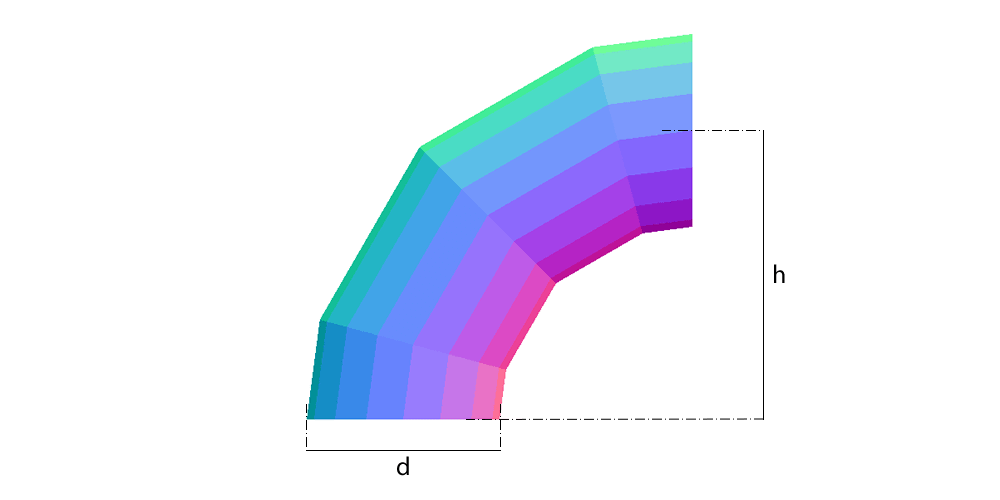
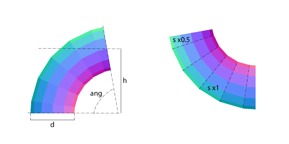
In Planichapa the gore count is the number of ANGULAR segments: each turns 90°/gores. With 3 gores you get 2 half gores and 2 full gores; with 4, 2 halves and 3 fulls. The classic shop bend of three gores and two half gores is therefore gores = 4 here, each segment turning 22.5°.
| Gores entered | Half gores | Full gores | Turn per segment | Half-mitre β |
|---|---|---|---|---|
| 2 | 2 | 1 | 45° | 22.5° |
| 3 | 2 | 2 | 30° | 15° |
| 4 (3 full and 2 halves) | 2 | 3 | 22.5° | 11.25° |
| 5 | 2 | 4 | 18° | 9° |
| 6 | 2 | 5 | 15° | 7.5° |
The segmented bend formula
- Mean radius and plate length
r = (D − t) / 2 ; L = π × (D − t)In the example: r = 395 mm and L = 2481.9 mm. Every gore is a rolled shell, and its plate develops on the neutral axis like any shell.
- Half-mitre
β = 90° / (2 × gores) = 45° / goresWith 3 gores, β = 15°. It is the cut angle of each half gore from square; the full gore has that cut at both ends.
- Cut height at each element
y(φ) = (R + r × cos φ) × tan βφ is the angle round the tube, φ = 0 at the heel (outside of the bend) and φ = 180° at the throat. The height is greatest at the heel and least at the throat.
- Heel and throat
y_heel = (R + r) × tan β ; y_throat = (R − r) × tan βIn the example: 1595 × 0.2679 = 427.4 mm and 805 × 0.2679 = 215.7 mm. The sine wave swings between those two values.
- Full gore
height = 2 × y(φ)854.8 mm at the heel and 431.4 mm at the throat in the example.
Worked example: ordinate table
With D = 800, 10 mm plate, R = 1200 and 3 gores (β = 15°, tan β = 0.2679), the half-gore height at each element, every 22.5° round the tube:
| φ (from the heel) | R + r × cos φ | Half-gore height y(φ) | Full-gore height |
|---|---|---|---|
| 0° (heel) | 1595.0 | 427.4 mm | 854.8 mm |
| 45° | 1479.3 | 396.4 mm | 792.8 mm |
| 90° | 1200.0 | 321.5 mm | 643.1 mm |
| 135° | 920.7 | 246.7 mm | 493.4 mm |
| 180° (throat) | 805.0 | 215.7 mm | 431.4 mm |
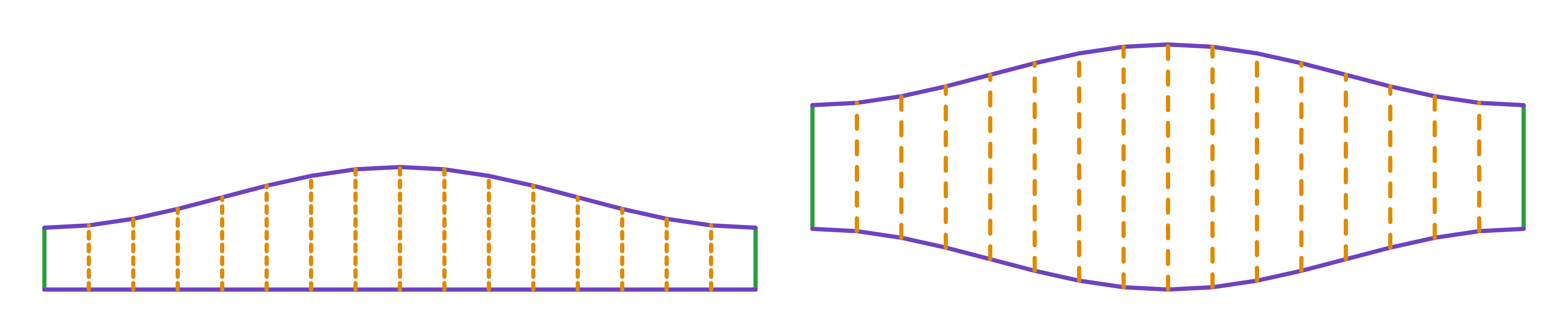
The half-gore plate measures 2482 × 427 mm and is cut twice; the full-gore plate measures 2482 × 855 mm and is cut twice (gores − 1). Four plates, one bend.
Marking out on the plate
- Work out β and the heights y(φ) for the dv elements, or copy the calculator's table. For the three-gore, two-half-gore bend, enter gores = 4.
- Mark the half-gore rectangle: L = π × (D − t) long by y_heel high. Divide the length into dv equal parts (16 in the example, one every 155.1 mm): each division is an element.
- Mark the height y(φ) on each element from the base. The heel goes at one edge of the plate and the throat in the middle: the longitudinal seam will sit on the heel, where the weld is longer but clear of the throat.
- Join the points with a flexible rule. The edge is a sine wave of amplitude 2 × r × tan β, 211.6 mm in the example.
- For the full gore, mark the rectangle at twice the height and mirror the same sine wave on both edges.
- Cut 2 half gores and (gores − 1) full gores. Roll each as a shell, pre-bending the ends.
- Assemble turning each gore half a turn against its neighbour, so the longitudinal seams sit 180° apart, and tack before welding the circumferential joints. Check the angle with a square on both openings.
Mistakes that leave the bend crooked
- Counting the half gores as gores. The three-gore, two-half-gore bend has four segments of 22.5°; entering 3 gives 30° segments and a coarser bend, with the heel 110 mm higher per plate.
- Measuring the radius at the throat or the heel. R is the radius at the AXIS. The heel sits at R + D/2 and the throat at R − D/2: entering the throat radius as R gives a bend 400 mm tighter in the example.
- Seams in line. With all the longitudinal seams on one side the bend assembles crooked and the longitudinal weld runs into the circumferential one; turning each gore half a turn fixes it.
- Using π × D for the length. The rolled-shell mistake: π × t extra on every gore, 31.4 mm in the example in 10 mm plate, and every circumferential joint overlaps.
- Too few elements. With 8 divisions the sine wave turns into facets and the mouth does not seat on the next gore. Sixteen is the comfortable minimum at 800 mm; 32 on large diameters.
- Radius under half the diameter. The gores cross at the throat and there is no part; the calculation refuses it.
Other bends
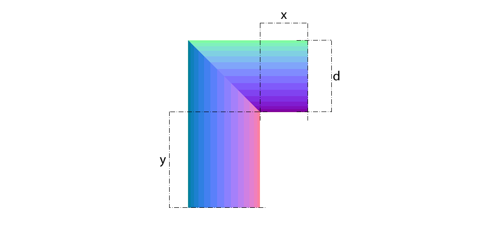
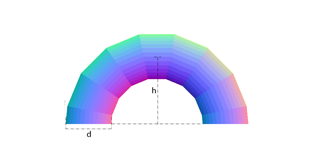
The same formula serves any angle: on the free segmented bend you enter the angle, and on the 180° bend it is locked at the full return, with β = 90°/gores. The elbow is the gores = 1 case: two half gores cut at 45°, no full gore. For rectangular duct there is the rectangular duct bend, and for flat-oval duct the oval segmented bend.
Frequently asked questions
- How do I work out a 90° segmented bend?
- Divide 90° by the gore count for the turn of each segment; the half-mitre is half of that, β = 45°/gores. The cut height at each element is (R + r × cos φ) × tan β, with R the axis radius and r = (D − t)/2. The plate length is π × (D − t).
- How many gores does a 90° bend have?
- It depends on the finish: three gores and two half gores (four segments of 22.5°) is the classic duct layout; five to six segments for process pipework. More gores give a smoother bend and less pressure loss, but more cuts and more welding.
- What is the difference between a full gore and a half gore?
- The half gore is the end of the bend, cut at an angle at one end only; the full gore is a middle piece cut at both ends, twice the height of the half gore. Every bend has 2 half gores and (segments − 1) full gores.
- Where does the longitudinal seam of a gore go?
- On the heel or the throat, alternating: each gore is turned half a turn against its neighbour so the seams do not line up. In line, the longitudinal weld runs into the circumferential one.
- Is a segmented bend suitable for pressure?
- The geometry is the same, but the welded segmented bend is a duct and low-pressure pipework part. For vessels and pressure piping the code calls for forged bends or limits the angle per gore; the development does not change, the code does.