90° Segmented Bend development
What it is
The segmented bend with its angle fixed at 90 degrees — the mitred elbow of ductwork, the most common case in practice, with the angle field locked so it cannot be mistyped. Everything else works as the free segmented bend: you choose diameter, radius and gore count.
Where it is used
Direction changes in exhaust and ventilation ducting, large-diameter elbows fabricated from plate.
Measurements the calculation needs
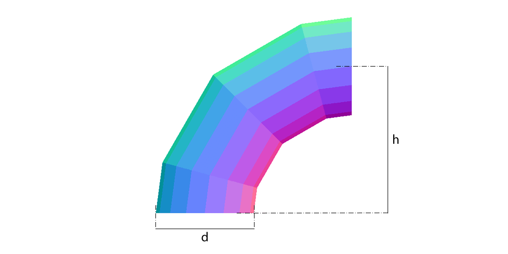
- H Bend radius (to the tube axis)
- D Outside diameter of the tube
- ANG Angle of the bend (fixed at 90°)
- S Number of gores
- DV Divisions
- THK Plate thickness
Calculate with your own measurements
No account needed: enter the measurements in millimetres and get the figures and the drawing. The scaled PDF template, the DXF for the cutting table and the 3D model take a free account.
How it develops: the formulas
- Half-mitre
β = 45° / gores3 gores: 15°; 4 gores: 11.25°; 5 gores: 9°. Each middle gore turns 2β and the end gores turn β.- Cut height at each element
y(φ) = (R + r × cos φ) × tan βr = (D − t)/2 and R the axis radius. For D = 800, 10 mm plate, R = 1200 and 3 gores: throat 215.7 mm and heel 427.4 mm on the end gore; the middle gore is double, 855 mm.- Plate length
L = π × (D − t)2481.9 mm in the example.- Shop gores
3 gores plus 2 half gores = gores 4Here gores is the number of angular segments, each turning 90°/gores. The plates are 2 half ends and (gores − 1) full gores.
Worked example
The values the form comes pre-filled with, run through the tool itself:
| Bend radius (to the tube axis) | 1200 mm |
|---|---|
| Outside diameter of the tube | 800 mm |
| Angle of the bend (fixed at 90°) | 90° |
| Number of gores | 3 |
| Divisions | 16 |
| Plate thickness | 10 mm |
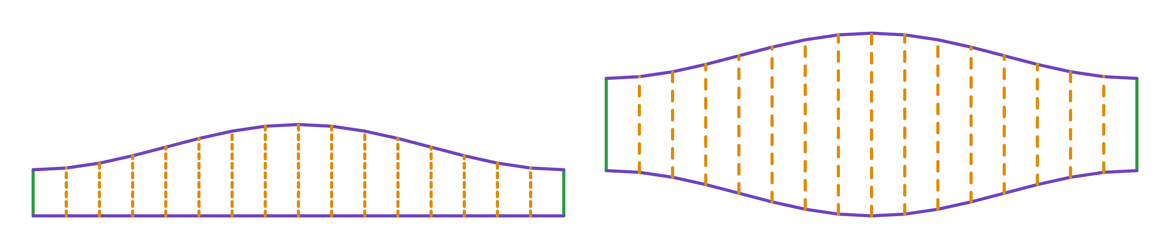
| The flat pattern fits a plate of | 2482 × 855 mm |
| Flat patterns produced | 2 |
Result of the example
| Plate 1 | 2482 × 427 mm, cut 2 times |
|---|---|
| Plate 2 | 2482 × 855 mm, cut 2 times |
Assembly notes
Weld the sheets with the longitudinal seams 180° apart, not lined up. Lined up, the piece assembles into a different shape — and the longitudinal seam crosses the circumferential one.
How to mark it out on the plate
- Choose the gore count and work out β = 45°/gores; for the classic 3 gores plus 2 half gores, enter 4.
- Mark the rectangle of L by (R + r) × tan β, divide it into dv elements and mark y(φ) on each; join with a flexible rule.
- Mirror the wave for the middle gore (double height) and cut 2 ends and (gores − 1) middles.
- Roll, assemble with the seams 180° apart and weld the circumferential joints.
Common mistakes and tolerances
- Counting the half gores as gores
- The bend with 3 gores and 2 half gores has 4 angular segments of 22.5°. Entering gores = 3 gives 3 segments of 30° and a coarser bend.
- Radius under half the diameter
- R < D/2 makes the gores cross at the throat; the calculation refuses it. For 90° duct bends, R of 1 to 1.5 × D is usual.
- Seams in line
- Turn each gore half a turn from its neighbour. In line, the longitudinal weld runs into the circumferential one and the bend assembles crooked.
Guides about this part
Frequently asked questions
- How does this differ from the general segmented bend?
- Not at all in the calculation: it is the same part with the angle pinned to 90 degrees. It exists separately to avoid mistyping the angle, which is the field that causes the most rework.
- Can I use only two gores?
- You can, and the result is the simple two-piece elbow. Above that the bend gets smoother and pressure loss drops.
- Which number is the shop's 3 gores plus 2 half gores here?
- Gores = 4. Here gores is the number of angular segments, each of 90°/gores; the plates are 2 half ends and gores − 1 full gores. With 4, each segment turns 22.5° and the half-mitre is 11.25°.
- How high is the cut in the example?
- For 800 diameter, 10 mm plate, radius 1200 and 3 gores: 215.7 mm at the throat and 427.4 mm at the heel of the end gore. The middle gore is double: 855 mm at the heel.
You can work out the figures right here, with no account. PDF, DXF, 3D and history take an account; the free tier covers 20 calculations a month.