Pipe Offset (Portal) development
What it is
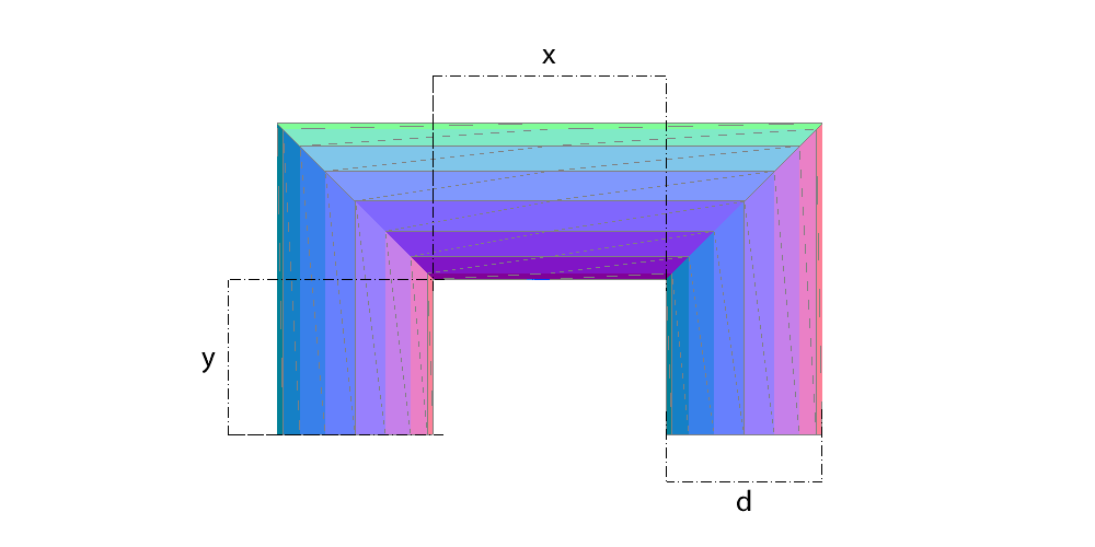
The portal is the U-shaped part: two elbows joined by a straight run, solved together so the cuts match. The result comes as four flat patterns, one per segment.
Where it is used
Pipe offsets around obstructions, crossings over beams and walkways, ducting that must step aside and return to the same line.
Measurements the calculation needs
- D Outside diameter of the tube
- X Clear span between the legs
- Y Clear height under the crossbar
- DV Divisions
- THK Plate thickness
Worked example
The values the form comes pre-filled with, run through the tool itself:
| Outside diameter of the tube | 200 mm |
|---|---|
| Clear span between the legs | 300 mm |
| Clear height under the crossbar | 200 mm |
| Divisions | 16 |
| Plate thickness | 10 mm |
| The flat pattern fits a plate of | 597 × 395 mm |
| Flat patterns produced | 4 |
Result of the example
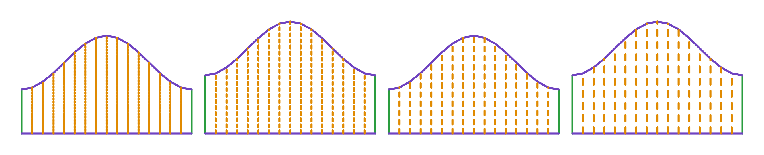
| Plate 1 | 597 × 345 mm |
|---|---|
| Plate 2 | 597 × 395 mm |
| Plate 3 | 597 × 345 mm |
| Plate 4 | 597 × 395 mm |
Frequently asked questions
- Why four flat patterns?
- Each of the four parts of the U — the two bends and the pieces joining them — has its own development. They are calculated together so the cuts meet on assembly.
- How do I choose X and Y?
- X is the lateral step of the offset and Y the height. Together they set how far the portal displaces the run.
Calculate a Pipe Offset (Portal)
An account is required. The free tier covers 20 calculations a month.