90° Segmented Bend flat pattern
What it is
The segmented bend with its angle fixed at 90 degrees — the mitred elbow of ductwork, the most common case in practice, with the angle field locked so it cannot be mistyped. Everything else works as the free segmented bend: you choose diameter, radius and gore count.
Where it is used
Direction changes in exhaust and ventilation ducting, large-diameter elbows fabricated from plate.
Measurements the calculation needs
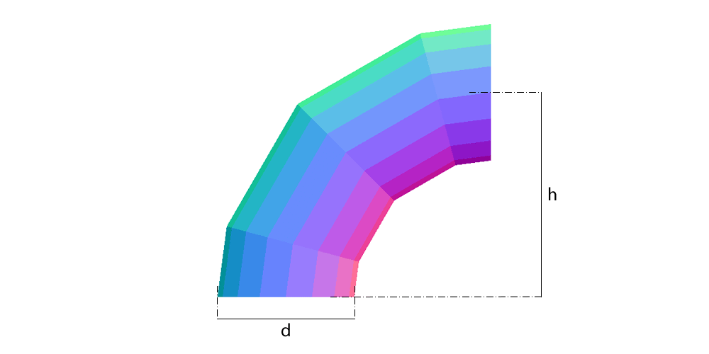
- H Bend radius (to the tube axis)
- D Outside diameter of the tube
- ANG Angle of the bend (fixed at 90°)
- S Number of gores
- DV Divisions
- THK Plate thickness
Calculate with your own measurements
No account needed: enter the measurements in millimetres or inches and get the figures and the drawing. The scaled PDF template, the DXF for the cutting table and the 3D model take a free account.
Diameters and sides are outside measurements. The flat pattern already allows for the plate thickness, working on the mean line.
Units: mm inches
How it develops: the formulas
- Half-mitre
β = 45° / gores3 gores: 15°; 4 gores: 11.25°; 5 gores: 9°. Each middle gore turns 2β and the end gores turn β.- Cut height at each element
y(φ) = (R + r × cos φ) × tan βr = (D − t)/2 and R the axis radius. For D = 800, 10 mm plate, R = 1200 and 3 gores: throat 215.7 mm and heel 427.4 mm on the end gore; the middle gore is double, 855 mm.- Plate length
L = π × (D − t)2481.9 mm in the example.- Shop gores
3 gores plus 2 half gores = gores 4Here gores is the number of angular segments, each turning 90°/gores. The plates are 2 half ends and (gores − 1) full gores.
Worked example
The values the form comes pre-filled with, run through the tool itself:
| Bend radius (to the tube axis) | 47-1/4" (47.2441) |
|---|---|
| Outside diameter of the tube | 31-1/2" (31.4961) |
| Angle of the bend (fixed at 90°) | 90° |
| Number of gores | 3 |
| Divisions | 16 |
| Plate thickness | 3/8" (0.3937) |
| The flat pattern fits a plate of | 97-11/16" × 33-5/8" |
| Flat patterns produced | 2 |
Result of the example
| Plate 1 | 97-11/16" × 16-13/16", cut 2 times |
|---|---|
| Area and weight | 8.6 ft² · ≈ 138.1 lb in 3/8" steel |
| Plate 2 | 97-11/16" × 33-5/8", cut 2 times |
| Area and weight | 17.2 ft² · ≈ 276.2 lb in 3/8" steel |
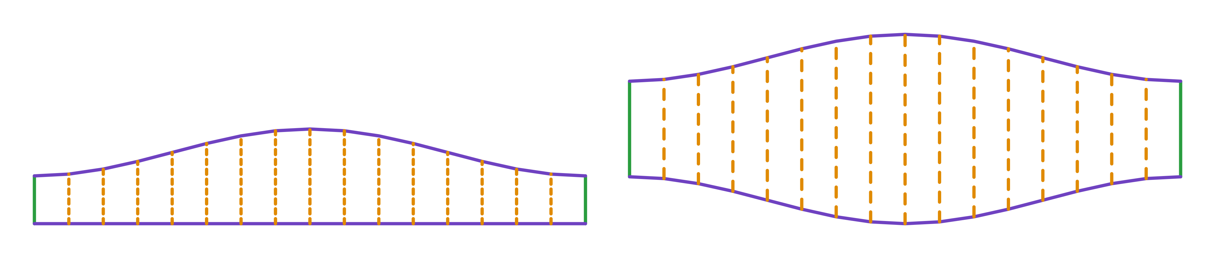
Ordinate table
| # | Position on the plate | Element height |
|---|---|---|
| 1 | 0" | 8-1/2" |
| 2 | 6-1/8" | 8-13/16" |
| 3 | 12-3/16" | 9-11/16" |
| 4 | 18-5/16" | 11-1/16" |
| 5 | 24-7/16" | 12-11/16" |
| 6 | 30-9/16" | 14-1/4" |
| 7 | 36-5/8" | 15-5/8" |
| 8 | 42-3/4" | 16-1/2" |
| 9 | 48-7/8" | 16-13/16" |
| 10 | 54-15/16" | 16-1/2" |
| 11 | 61-1/16" | 15-5/8" |
| 12 | 67-3/16" | 14-1/4" |
| 13 | 73-5/16" | 12-11/16" |
| 14 | 79-3/8" | 11-1/16" |
| 15 | 85-1/2" | 9-11/16" |
| 16 | 91-5/8" | 8-13/16" |
| 17 | 97-11/16" | 8-1/2" |
Assembly notes
Every gore comes with its longitudinal seam on the throat, the shortest weld, and the gores go together all the same way round, heel to heel. Do not turn a cut gore half a turn to stagger the seams: its long side goes to the throat and the bend loses angle. To stagger them, mark every second gore from the heel instead — cut the paper template on its middle line and swap the two halves.
How to mark it out on the plate
- Choose the gore count and work out β = 45°/gores; for the classic 3 gores plus 2 half gores, enter 4.
- Mark the rectangle of L by (R + r) × tan β, divide it into dv elements and mark y(φ) on each; join with a flexible rule.
- Mirror the wave for the middle gore (double height) and cut 2 ends and (gores − 1) middles.
- Roll, assemble heel to heel and weld the circumferential joints; for staggered seams, mark every second gore from the heel.
Common mistakes and tolerances
- Counting the half gores as gores
- The bend with 3 gores and 2 half gores has 4 angular segments of 22.5°. Entering gores = 3 gives 3 segments of 30° and a coarser bend.
- Radius under half the diameter
- R < D/2 makes the gores cross at the throat; the calculation refuses it. For 90° duct bends, R of 1 to 1.5 × D is usual.
- Turning a gore half a turn
- It puts the gore's long side on the throat and the bend loses angle. To stagger the seams, mark every second gore from the heel.
Guides about this part
- Lobster back bend calculator (segmented 90° elbow): gore angles, cut heights and how many plates
- LITIO alternative: Planichapa develops sheet metal parts in the browser, nothing to install, now that LITIO2 is no longer sold
- Plate 'n' Sheet alternative: Planichapa develops sheet metal parts in the browser, with the price on the page
- Pipe ovality: a calculator, the formula, a worked example, the limits the codes use and how to measure it in the shop
- Sheet metal pattern development software: how to choose, and what changes between a desktop program, a phone app and an online calculator
- Pie cut calculator for exhaust and tube bends: saw angle, pie lengths and a wrap-around template
Frequently asked questions
- How does this differ from the general segmented bend?
- Not at all in the calculation: it is the same part with the angle pinned to 90 degrees. It exists separately to avoid mistyping the angle, which is the field that causes the most rework.
- Can I use only two gores?
- You can, and the result is the simple two-piece elbow. Above that the bend gets smoother and pressure loss drops.
- Which number is the shop's 3 gores plus 2 half gores here?
- Gores = 4. Here gores is the number of angular segments, each of 90°/gores; the plates are 2 half ends and gores − 1 full gores. With 4, each segment turns 22.5° and the half-mitre is 11.25°.
- How high is the cut in the example?
- For 800 diameter, 10 mm plate, radius 1200 and 3 gores: 215.7 mm at the throat and 427.4 mm at the heel of the end gore. The middle gore is double: 855 mm at the heel.
You can work out the figures right here, with no account. PDF, DXF, 3D and history take an account — free, with unlimited calculations.