Flange bolt circle layout
What it is
The plate flange is the drilled ring that joins two pipes, fixes a pipe to a piece of equipment or closes an opening as a blind flange. Like the chain sprocket, it is born flat: the calculation develops nothing, and returns the outline, the position of every hole and the chord for stepping out the drilling with dividers. The ASME B16.5 (classes 150 and 300) and EN 1092-1 (PN 10 and PN 16) drillings fill in the dimensions with one click.
Where it is used
Low-pressure pipework flanges, round ventilation and exhaust duct flanges, tank and silo nozzles, equipment flanges -- pump, fan, valve -- and blind inspection covers.
Measurements the calculation needs
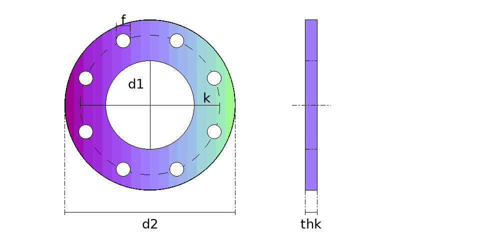
- D1 Bore (0 for a blind flange)
- D2 Outside diameter
- K Bolt circle
- NF Number of holes
- F Hole diameter
- THK Plate thickness
Calculate with your own measurements
No account needed: enter the measurements in millimetres or inches and get the figures and the drawing. The scaled PDF template, the DXF for the cutting table and the 3D model take a free account.
Inches or millimetres? mm inches
Flange drilling by standard
The drilling of the most used standards, to check against or to fill in the calculator in one click. The calculator bore is the pipe outside diameter; the fit-up clearance is yours to add.
ASME B16.5 classe 150
| Size | Outside | Bolt circle | Holes | Hole Ø | Pipe | |
|---|---|---|---|---|---|---|
| NPS 1/2 | 88.9 | 60.3 | 4 | 15.9 | 21.3 | Calculate |
| NPS 3/4 | 98.4 | 69.9 | 4 | 15.9 | 26.7 | Calculate |
| NPS 1 | 108.0 | 79.4 | 4 | 15.9 | 33.4 | Calculate |
| NPS 1-1/4 | 117.5 | 88.9 | 4 | 15.9 | 42.2 | Calculate |
| NPS 1-1/2 | 127.0 | 98.4 | 4 | 15.9 | 48.3 | Calculate |
| NPS 2 | 152.4 | 120.7 | 4 | 19.1 | 60.3 | Calculate |
| NPS 2-1/2 | 177.8 | 139.7 | 4 | 19.1 | 73.0 | Calculate |
| NPS 3 | 190.5 | 152.4 | 4 | 19.1 | 88.9 | Calculate |
| NPS 3-1/2 | 215.9 | 177.8 | 8 | 19.1 | 101.6 | Calculate |
| NPS 4 | 228.6 | 190.5 | 8 | 19.1 | 114.3 | Calculate |
| NPS 5 | 254.0 | 215.9 | 8 | 22.2 | 141.3 | Calculate |
| NPS 6 | 279.4 | 241.3 | 8 | 22.2 | 168.3 | Calculate |
| NPS 8 | 342.9 | 298.5 | 8 | 22.2 | 219.1 | Calculate |
| NPS 10 | 406.4 | 362.0 | 12 | 25.4 | 273.0 | Calculate |
| NPS 12 | 482.6 | 431.8 | 12 | 25.4 | 323.8 | Calculate |
| NPS 14 | 533.4 | 476.3 | 12 | 28.6 | 355.6 | Calculate |
| NPS 16 | 596.9 | 539.8 | 16 | 28.6 | 406.4 | Calculate |
| NPS 18 | 635.0 | 577.9 | 16 | 31.8 | 457.2 | Calculate |
| NPS 20 | 698.5 | 635.0 | 20 | 31.8 | 508.0 | Calculate |
| NPS 24 | 812.8 | 749.3 | 20 | 34.9 | 609.6 | Calculate |
ASME B16.5 classe 300
| Size | Outside | Bolt circle | Holes | Hole Ø | Pipe | |
|---|---|---|---|---|---|---|
| NPS 1/2 | 95.3 | 66.7 | 4 | 15.9 | 21.3 | Calculate |
| NPS 3/4 | 117.5 | 82.6 | 4 | 19.1 | 26.7 | Calculate |
| NPS 1 | 123.8 | 88.9 | 4 | 19.1 | 33.4 | Calculate |
| NPS 1-1/4 | 133.4 | 98.4 | 4 | 19.1 | 42.2 | Calculate |
| NPS 1-1/2 | 155.6 | 114.3 | 4 | 22.2 | 48.3 | Calculate |
| NPS 2 | 165.1 | 127.0 | 8 | 19.1 | 60.3 | Calculate |
| NPS 2-1/2 | 190.5 | 149.2 | 8 | 22.2 | 73.0 | Calculate |
| NPS 3 | 209.6 | 168.3 | 8 | 22.2 | 88.9 | Calculate |
| NPS 3-1/2 | 228.6 | 184.2 | 8 | 22.2 | 101.6 | Calculate |
| NPS 4 | 254.0 | 200.0 | 8 | 22.2 | 114.3 | Calculate |
| NPS 5 | 279.4 | 235.0 | 8 | 22.2 | 141.3 | Calculate |
| NPS 6 | 317.5 | 269.9 | 12 | 22.2 | 168.3 | Calculate |
| NPS 8 | 381.0 | 330.2 | 12 | 25.4 | 219.1 | Calculate |
| NPS 10 | 444.5 | 387.4 | 16 | 28.6 | 273.0 | Calculate |
| NPS 12 | 520.7 | 450.9 | 16 | 31.8 | 323.8 | Calculate |
| NPS 14 | 584.2 | 514.4 | 20 | 31.8 | 355.6 | Calculate |
| NPS 16 | 647.7 | 571.5 | 20 | 34.9 | 406.4 | Calculate |
| NPS 18 | 711.2 | 628.7 | 24 | 34.9 | 457.2 | Calculate |
| NPS 20 | 774.7 | 685.8 | 24 | 34.9 | 508.0 | Calculate |
| NPS 24 | 914.4 | 812.8 | 24 | 41.3 | 609.6 | Calculate |
EN 1092-1 PN 10
| Size | Outside | Bolt circle | Holes | Hole Ø | Pipe | |
|---|---|---|---|---|---|---|
| DN 15 | 95.0 | 65.0 | 4 | 14.0 | 21.3 | Calculate |
| DN 20 | 105.0 | 75.0 | 4 | 14.0 | 26.9 | Calculate |
| DN 25 | 115.0 | 85.0 | 4 | 14.0 | 33.7 | Calculate |
| DN 32 | 140.0 | 100.0 | 4 | 18.0 | 42.4 | Calculate |
| DN 40 | 150.0 | 110.0 | 4 | 18.0 | 48.3 | Calculate |
| DN 50 | 165.0 | 125.0 | 4 | 18.0 | 60.3 | Calculate |
| DN 65 | 185.0 | 145.0 | 8 | 18.0 | 76.1 | Calculate |
| DN 80 | 200.0 | 160.0 | 8 | 18.0 | 88.9 | Calculate |
| DN 100 | 220.0 | 180.0 | 8 | 18.0 | 114.3 | Calculate |
| DN 125 | 250.0 | 210.0 | 8 | 18.0 | 139.7 | Calculate |
| DN 150 | 285.0 | 240.0 | 8 | 22.0 | 168.3 | Calculate |
| DN 200 | 340.0 | 295.0 | 8 | 22.0 | 219.1 | Calculate |
| DN 250 | 395.0 | 350.0 | 12 | 22.0 | 273.0 | Calculate |
| DN 300 | 445.0 | 400.0 | 12 | 22.0 | 323.9 | Calculate |
| DN 350 | 505.0 | 460.0 | 16 | 22.0 | 355.6 | Calculate |
| DN 400 | 565.0 | 515.0 | 16 | 26.0 | 406.4 | Calculate |
| DN 450 | 615.0 | 565.0 | 20 | 26.0 | 457.0 | Calculate |
| DN 500 | 670.0 | 620.0 | 20 | 26.0 | 508.0 | Calculate |
| DN 600 | 780.0 | 725.0 | 20 | 30.0 | 610.0 | Calculate |
EN 1092-1 PN 16
| Size | Outside | Bolt circle | Holes | Hole Ø | Pipe | |
|---|---|---|---|---|---|---|
| DN 15 | 95.0 | 65.0 | 4 | 14.0 | 21.3 | Calculate |
| DN 20 | 105.0 | 75.0 | 4 | 14.0 | 26.9 | Calculate |
| DN 25 | 115.0 | 85.0 | 4 | 14.0 | 33.7 | Calculate |
| DN 32 | 140.0 | 100.0 | 4 | 18.0 | 42.4 | Calculate |
| DN 40 | 150.0 | 110.0 | 4 | 18.0 | 48.3 | Calculate |
| DN 50 | 165.0 | 125.0 | 4 | 18.0 | 60.3 | Calculate |
| DN 65 | 185.0 | 145.0 | 8 | 18.0 | 76.1 | Calculate |
| DN 80 | 200.0 | 160.0 | 8 | 18.0 | 88.9 | Calculate |
| DN 100 | 220.0 | 180.0 | 8 | 18.0 | 114.3 | Calculate |
| DN 125 | 250.0 | 210.0 | 8 | 18.0 | 139.7 | Calculate |
| DN 150 | 285.0 | 240.0 | 8 | 22.0 | 168.3 | Calculate |
| DN 200 | 340.0 | 295.0 | 12 | 22.0 | 219.1 | Calculate |
| DN 250 | 405.0 | 355.0 | 12 | 26.0 | 273.0 | Calculate |
| DN 300 | 460.0 | 410.0 | 12 | 26.0 | 323.9 | Calculate |
| DN 350 | 520.0 | 470.0 | 16 | 26.0 | 355.6 | Calculate |
| DN 400 | 580.0 | 525.0 | 16 | 30.0 | 406.4 | Calculate |
| DN 450 | 640.0 | 585.0 | 20 | 30.0 | 457.0 | Calculate |
| DN 500 | 715.0 | 650.0 | 20 | 33.0 | 508.0 | Calculate |
| DN 600 | 840.0 | 770.0 | 20 | 36.0 | 610.0 | Calculate |
Dimensions in mm. ASME B16.5 is in inches and was converted from the exact fraction; EN 1092-1 is in millimetres. Checked against manufacturers’ catalogues: for a pressure flange, check against the standard or the mating flange.
How it develops: the formulas
- Pitch between holes
β = 360° / nn is the number of holes. With 8 holes, 45°.- Position of each hole
θi = (i + ½) × β ; xi = (K / 2) × cos θi ; yi = (K / 2) × sin θiK is the bolt circle. The first hole sits half a pitch from the centre line: in the example at 22.5°, at x = 83.1 and y = 34.4 mm from the centre.- Chord between neighbouring holes
c = K × sin(180° / n)For K = 180 and 8 holes: c = 68.9 mm. It is the divider setting that steps out the bolt circle.- The holes do not touch
c > F ; K − F > d ; K + F < DF is the hole diameter, d the bore and D the outside diameter. In the example: 68.9 > 18, 162 > 114.3 and 198 < 220.
Worked example
The values the form comes pre-filled with, run through the tool itself:
| Bore (0 for a blind flange) | 114.3 mm |
|---|---|
| Outside diameter | 220 mm |
| Bolt circle | 180 mm |
| Number of holes | 8 |
| Hole diameter | 18 mm |
| Plate thickness | 16 mm |
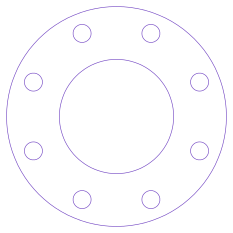
| The flat pattern fits a plate of | 220 × 220 mm |
Result of the example
| Plate | 220 × 220 mm |
|---|---|
| Area and weight | 0.026 m² · ≈ 3.2 kg in 16 mm steel |
| Arc radii | 9 mm · 57.2 mm · 110 mm |
| Sector angle | 360° |
Assembly notes
The 8 holes sit every 45° on the bolt circle, OFF the centre lines: the first one 22.5° from the centre line, as flange standards place them, so that the flange mates with its counterpart in any symmetric position. To mark them without a protractor, set the dividers to the 68.9 mm chord between neighbouring centres and step round the circle; the last step must land on the first hole.
How to mark it out on the plate
- Choose the standard and size in the selector, or type in the dimensions of the mating flange.
- From one centre, scribe the outside diameter, the bore and the bolt circle.
- Mark the first hole half a pitch from the centre line -- 22.5° with 8 holes -- and, with the dividers set to the chord, step round the circle. The last step must land on the first hole; if it overshoots or falls short, the setting is wrong.
- Cut the outside and the bore, and make the holes. A plasma hole smaller than one and a half times the thickness comes out tapered: mark the centre and drill.
- Offer the flange up to its counterpart and pass the bolts before welding.
Common mistakes and tolerances
- A hole on the centre line
- The standards put the holes OFF the centre lines, half a pitch from them. With a hole on the vertical, the flange sits half a pitch rotated from its counterpart, and the valve or equipment goes in crooked.
- Mixing up class and PN
- ASME class 150 and EN PN 16 do not mate: on 4 inch pipe the bolt circle is 190.5 in one and 180 in the other. Check the standard of the mating flange before choosing.
- A bore with no clearance
- Filling in from a standard sets the bore to the pipe outside diameter. For a slip-on flange, add the clearance your weld needs, usually 1.5 to 3 mm on the diameter.
- Plasma holes in thick plate
- Below about one and a half times the thickness, a plasma hole comes out tapered and oval, and the bolt either does not pass or passes loose. The template gives the centre; drill or ream.
Guides about this part
Frequently asked questions
- Will this flange do for pressure piping?
- The drilling will: it is the standard one, and it is what makes the flange mate with its counterpart. The ASME B16.5 pressure flange is forged, with a specified hub, face and material, and that is what pressure piping calls for. The plate flange is for low pressure, ducts, tanks and equipment.
- Why is the bore the same as the pipe?
- Because the standard gives the pipe outside diameter -- by ASME B36.10 or EN 10220. A slip-on flange needs clearance for the pipe to go in and for the weld; add what your procedure asks for, usually 1.5 to 3 mm on the diameter.
- Can I cut the holes by plasma?
- Yes, if the hole is well over the plate thickness. Below about one and a half times the thickness a plasma hole comes out tapered and oval; then use the template to mark the centre and drill.
- What is the chord between holes in the example?
- For the 180 circle with 8 holes, DN 100 PN 16: 68.9 mm, with the first hole 22.5° from the centre line.
You can work out the figures right here, with no account. PDF, DXF, 3D and history take an account — free, with unlimited calculations.