How to lay out a mitre-cut pipe: paper template, sine wave and ordinate table
Updated on 17 September 2026
Cutting a pipe at an angle is the most basic layout in plate work after the straight rolled shell, and the one that teaches the parallel-line method: the straight edge of the cutting plane, unrolled, becomes a wave. It serves for the column foot standing on a sloping floor, for the discharge mouth, for the pipe that enters a wall at an angle and, cut twice, for the gore of any bend.
This guide gives the formula, the ordinate table of the example worked by Planichapa and the two ways of marking it out: on the flat plate, before rolling, and on the finished pipe, with a paper template.
The dimensions
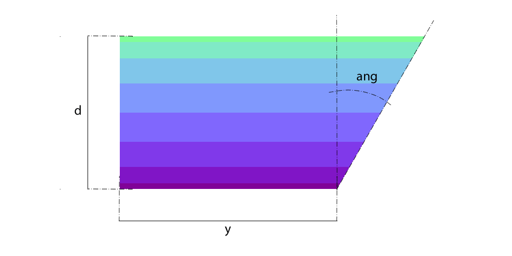
D is the outside diameter of the pipe, t the plate thickness, y the height of the short side (where the cutting plane meets the pipe), α the cut angle measured from the horizontal, and dv the number of elements the pipe is divided into for the layout. In the example: D = 200 mm, 10 mm plate, y = 50 mm, α = 40° and 16 elements.
The angle has to stay below 90°: at 90° the plane is parallel to the axis and cuts no mouth at all. And the long side comes out of the arithmetic; it is not entered.
The sine-wave formula
- Plate length
L = π × (D − t)The circumference on the neutral axis: 596.9 mm in the example. If the pipe already exists, a tape round the outside gives π × D, and the paper template uses that.
- Height at each element
z(φ) = y + (t/2) × tan α + r × tan α × (1 − cos φ)r = (D − t)/2 is the mean-surface radius, 95 mm, and φ the angle round the pipe from the short side. The term (t/2) × tan α is the thickness correction on the inclined cut: 4.2 mm in the example.
- Long side and amplitude
z_max = z(0) + (D − t) × tan αThe wave rises (D − t) × tan α from the short side to the long side: 190 × 0.839 = 159.4 mm. In the example the long side is 213.6 mm.
- Pitch between elements
p = L / dv37.3 mm with 16 divisions. Each element turns 360°/dv = 22.5°.
Worked example: ordinate table
| Element | φ | Position on the plate | Height z(φ) |
|---|---|---|---|
| 1 (short side, seam) | 0° | 0.0 mm | 54.2 mm |
| 3 | 45° | 74.6 mm | 77.5 mm |
| 5 | 90° | 149.2 mm | 133.9 mm |
| 7 | 135° | 223.8 mm | 190.3 mm |
| 9 (long side) | 180° | 298.5 mm | 213.6 mm |
| 11 | 225° | 373.1 mm | 190.3 mm |
| 13 | 270° | 447.7 mm | 133.9 mm |
| 15 | 315° | 522.3 mm | 77.5 mm |
| 17 (short side, seam) | 360° | 596.9 mm | 54.2 mm |
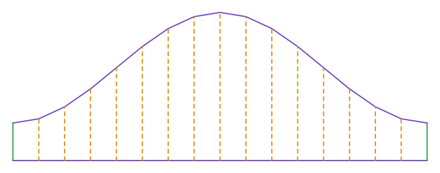
The wave is symmetrical about the long side: elements 3 and 15 have the same height. The plate of the example measures 597 × 214 mm, and the calculator gives all 17 ordinates at once.
Marking out on the flat plate
- Mark the rectangle L by z_max and divide L into dv equal parts. Number the elements from the seam, which sits on the short side.
- On each element mark the height z(φ), from the table or the calculator, up from the base.
- Join the points with a flexible rule. With 16 elements the sine wave comes out clean; with 8 it shows facets.
- Cut the curve, roll, and close the seam on the short side, the shortest element.
Marking out on the finished pipe, with a paper template
When the pipe already exists, no plate is rolled: the cut is marked straight onto it. The template is the same sine wave, drawn on paper or thin sheet with the OUTSIDE circumference, π × D, because it is the outer surface the paper wraps. The ordinates are the same, measured from a base line marked square round the pipe.
- Scribe a base line square round the pipe, with a centre square or a strip of paper.
- Draw the sine wave on paper with length π × D and the ordinates from the table; cut the paper along the curve.
- Wrap the paper round the pipe with its base on the base line and the template's seam on a marked element; scribe the curve with a scriber or chalk.
- Cut with oxy-fuel or plasma following the line, with the torch always pointed at the pipe axis so the bevel comes out uniform.
The paper template uses π × D, the flat-plate template uses π × (D − t). They are the same sine wave on two different circumferences, and swapping one for the other gives a wave that does not close round the pipe.
Two cuts: the elbow and the gore
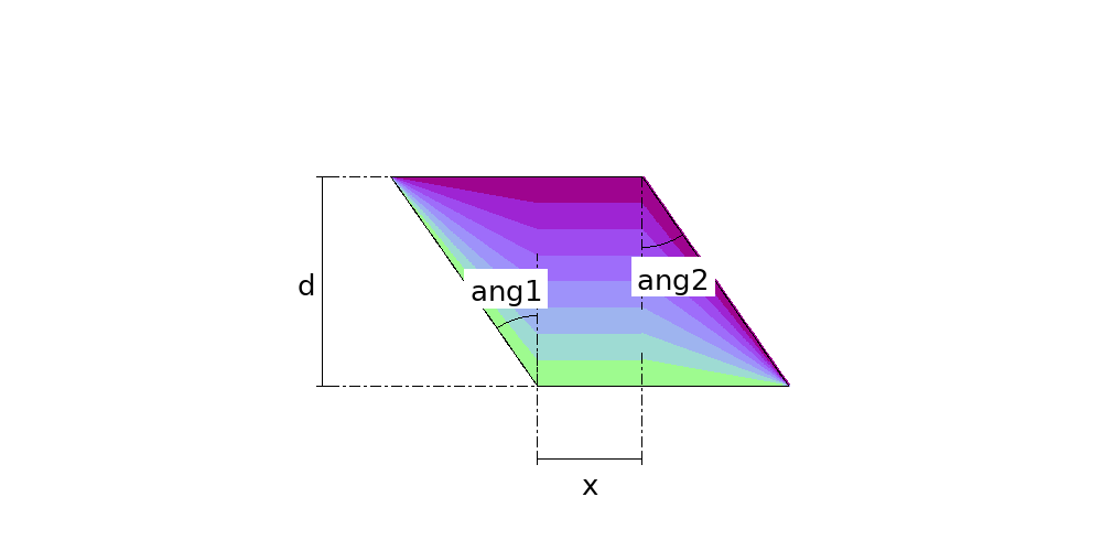
A pipe cut at both ends, each at its own angle, is the double cut cylinder: the gore of a bend assembled on site, or the length that takes up two changes of direction at once. Two pipes cut at 45° and welded together make the 90° elbow, with a single circumferential weld; and a run of gores cut at both ends makes the segmented bend, where the half-mitre β = angle/(2 × gores) plays the part of α here.
Common mistakes
- Entering the long side as y. y is the short side; the long one comes out of the formula. Swapping the two gives a part (D − t) × tan α taller than the order.
- Measuring the angle from the axis instead of the horizontal. A 45° cut is the same either way, but 30° on one is 60° on the other, and the wave amplitude changes from 0.58 to 1.73 times the diameter.
- Using the wrong circumference on the template: π × D on paper, π × (D − t) on the plate. One in place of the other gives π × t of difference, 31 mm in 10 mm plate.
- Joining the points with a straight edge. The sine wave between two elements is curved; with few divisions the cut comes out faceted and the mouth does not seat.
- Cutting with the torch perpendicular to the surface instead of pointed at the axis: the bevel comes out skewed and the mouth does not match the part it meets.
Frequently asked questions
- How do I lay out a pipe cut at 45 degrees?
- Divide the circumference into elements and mark on each the height z = y + r × (1 − cos φ), since tan 45° = 1: the wave rises exactly one diameter (on the mean surface, D − t) from the short side to the long side. Join the points with a flexible rule.
- Why does the cut edge become a wave?
- Because every point on the inclined mouth sits at a different height, and when the pipe is unrolled those heights spread along the circumference as a cosine. It is the intersection of a cylinder with a plane, and the curve is an exact sine wave.
- What is the difference between the paper template and the flat-plate one?
- The circumference. The paper wraps the outer surface, π × D; the flat plate develops on the neutral axis, π × (D − t). The ordinates are the same.
- Can I use the same layout for the elbow?
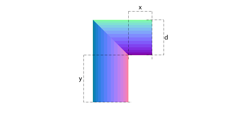
- Yes: the 90° elbow is two pipes cut at 45° and welded. Each half is this same layout with α = 45°, and the elbow's legs X and Y give the length of each half.
- How many elements should I use?
- Sixteen is usual up to 300 mm diameter; 24 or 32 on large pipes or in thin plate, where the facets show. The calculator accepts up to 128, in multiples of 4.
Parts in this guide
Other guides
- How to develop a cone (frustum) in sheet metal: formula, sector radii and angle, step by step
- Lobster back bend (segmented 90° elbow): gore angles, cut heights and how many plates
- Pipe saddle development: how to lay out a pipe-to-pipe branch (tee) at 90 and 45 degrees
- Square to round transition: development by triangulation, step by step
- The neutral axis of plate: why every development uses D − t, and the bend deduction
- Sheet metal glossary: the terms of marking out and pattern development in plate fabrication
- How we check the Planichapa calculations, and who is behind them
- Plate 'n' Sheet alternative: Planichapa develops sheet metal parts in the browser, with the price on the page
- Steel plate weight per m², gauges and stock plate sizes: weight table and formula
- Sheet metal pattern development software: how to choose, and what changes between a desktop program, a phone app and an online calculator
- Eccentric and concentric reducers: which one to use and how each one develops on plate