Duct transition layout: square to round duct, centred, offset or flat on one side
Updated on 28 October 2026
A duct transition joins two duct sizes, and the one laid out by hand most often is the square to round: a rectangular duct end becoming a round one. The Square to Round page lays it out in inches: set the page to inches and every result comes in fractions to the nearest 1/16 in, the thickness field takes a gauge from a list, and a free account adds the full-size template on Letter sheets and the DXF for the plasma table.
This page is the shop route: which of the three square to round pages fits the fitting on the drawing, what to measure, what the gauge changes, and what the pattern leaves for you to add. How the triangulation itself works, line by line, is in the square to round guide.
Which page for which transition
| The fitting | Page | What you type |
|---|---|---|
| Square to round, the round centred on the rectangle | Square to Round | The two sides X and Y, the round D, the length H and the gauge |
| Offset square to round: the round off centre, flat on one side or on two | Eccentric Rectangle to Round | The same, plus the offset of the round along X and along Y |
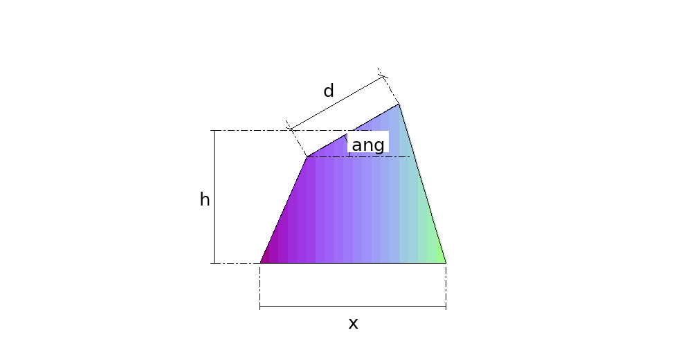
| Square to round with the round end tilted, not square to the duct | Inclined Square to Round | Square duct only, round centred and smaller than the side: the side, the round, the height to the centre of the round and the tilt |
| Rectangle to rectangle: reducer, offset, plenum transition | Rectangular Transition | Both rectangles and the length; the offset ones are in the plenum guide |
| Round duct leaving a rectangle sideways: the register boot | Angular Boot | See the register boot guide |
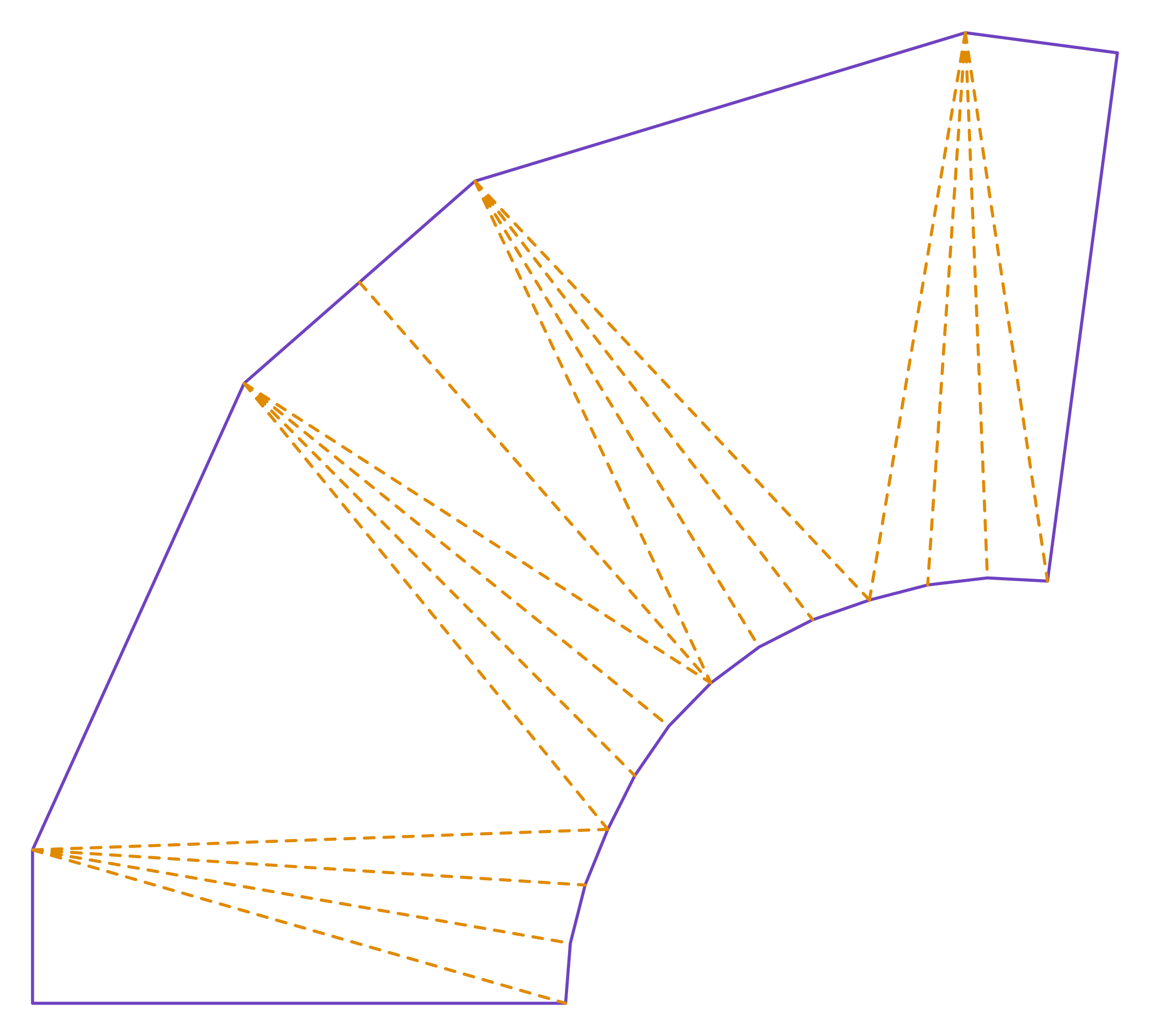
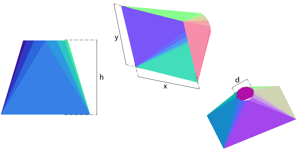
The three square to round pages build the same surface: a flat triangle on each side of the rectangle and a fan of lines at each corner, the fans carrying the curve. What changes is where the round sits. Centred, the four corners are alike, and the page develops half the fitting and mirrors it; off centre, every corner has its own true lengths, and the page walks the whole fitting round, once.
What to measure
| Field | On a duct transition |
|---|---|
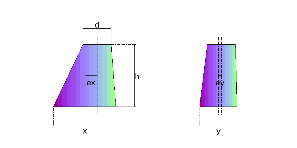
| X and Y, the rectangle | The duct size at the rectangular end: 24 and 12 for a 24 × 12 trunk. On the Square to Round page the seam falls in the middle of side Y, so give Y to the side that should carry it. |
| D, the round | The size of the round end: 10 for a 10 in round. |
| H, the length | From the rectangular end to the round end, square to both: the length of the fitting along the duct, not along its sloping side. |
| Offsets, eccentric page only | From the centre of the rectangle to the centre of the round, seen from above: one figure along X and one along Y. A negative figure moves the round the other way. |
| Thickness | The gauge, from the list. |
Type decimals: 10.5 for 10-1/2 in. Every size is an outside size, and the page works the pattern on the mean line, half the thickness in, so the fitting closes in the gauge you picked. On 26 gauge the outside of a 10 in round end is 0.04 in larger across than its inside, and 0.14 in larger round, about 1/8 in: enough to matter on a slip joint, so type the size the outside of each end has to be.
Offset, and flat on one side
Duct runs often need an offset transition: flat on top to run tight under the joists, flat on one side to hug a wall. On the Eccentric Rectangle to Round page that is an offset, and the offset that makes a side flat is half the difference between the duct and the round, across that side.
- Flat on one side
offset = (Y − D) / 2 along Y, or (X − D) / 2 along XAlong Y it flattens one of the two sides of length X; along X, one of the sides of length Y. A 24 × 12 duct, X 24 and Y 12, to a 10 in round, flat on a 24 in side: 1 in along Y and 0 along X. Flat on a 24 in side and on a 12 in side as well: 1 in along Y and 7 in along X.
The round has to stay inside the rectangle seen from above: the offset goes from zero up to that flush value and no further, and off centre the round cannot be wider than the narrow side of the duct. A 20 × 8 trunk to a 10 in round is still a normal fitting when centred, on the Square to Round page, where the flat triangles on the long sides lean out to meet the round; the eccentric page refuses it, centred or not. An offset that carries the round past the edge of the duct, to move the run over, is refused too, and no page here draws it.
Worked example: 24 × 12 to a 10 in round
A 24 × 12 in trunk (610 × 305 mm) to a 10 in round (254 mm), 12 in long (305 mm), in 26 gauge, 0.0217 in (0.55 mm).
| The fitting | What to type | Plate | Full-size template |
|---|---|---|---|
| Centred | Square to Round: X 24, Y 12, D 10, H 12 | 49-1/16 × 25-1/2 in (1246 × 647 mm) | 21 Letter sheets |
| Flat on one 24 in side | Eccentric Rectangle to Round: the same, with offsets X 0 and Y 1, DV 16 | 43-11/16 × 24-1/2 in (1110 × 623 mm) | 18 Letter sheets |
| Flat on a 24 in side and a 12 in side | The same, with offsets X 7 and Y 1 | 47-13/16 × 28-7/8 in (1214 × 733 mm) | 21 Letter sheets |
The three are the same fitting with the round moved, so the metal hardly changes; the shape of the blank does, because the page always starts the pattern at the seam. The centred pattern is the whole fitting with its seam in the middle of a 12 in side, and an orange line runs from the middle of the opposite 12 in side to the round: cut on it and you have the two equal halves of a two-piece fitting, one seam on each 12 in side. The eccentric pattern comes in one piece.
Gauge
The thickness field takes the gauge from a list. Galvanized sheet runs a little thicker than plain steel of the same number, because of the zinc:
| Galvanized gauge | Thickness | mm |
|---|---|---|
| 28 | 0.0187 in | 0.47 |
| 26 | 0.0217 in | 0.55 |
| 24 | 0.0276 in | 0.70 |
| 22 | 0.0336 in | 0.85 |
| 20 | 0.0396 in | 1.01 |
| 18 | 0.0516 in | 1.31 |
On duct gauges the thickness moves the pattern very little: from 26 to 24 gauge, the round end of the example changes by 0.02 in round. Which gauge a duct of a given size and pressure takes comes from the job spec or SMACNA's duct construction tables, not from this page.
What the pattern does not include
- Seam allowances. The pattern is net: the finished fitting on its mean line, with the seam edges butted. A Pittsburgh lock, a button punch snap lock, a standing seam or a lap for rivets or screws goes on along the seam edges, from the chart of your lock former: the allowance depends on the machine and the gauge, and the page does not guess it.
- End connections. No S and drive edge, no TDC or TDF connector and no hem on the rectangular end.
- Collars. No straight collar on either end, and no crimp or bead on the round end. A straight round collar is a plain band, on the Cylinder page; a straight run on the rectangular end is a strip folded along each side of the rectangle, added by hand.
- Lined duct. The metal is the clear inside size plus twice the liner: type the metal size.
- Offsets that take the round outside the rectangle, and an off-centre round wider than the narrow side of the duct.
For plasma or laser cutting, the free account exports 1 part a month in DXF; unlimited DXF export is the paid full access. Put the allowances on in your CAD before the DXF goes to the table, or along the edges of the paper template before you scribe.
Printing the template full size
- With a free account, enter the same figures in the full calculator and press 1:1 template on the result. In inches it comes on Letter sheets, with a cover page that maps them.
- Print at 100 %, actual size, portrait, with fit to page off. Measure the ruler at the foot of every sheet: it must read 4 in, or the printer scaled the page.
- Trim each sheet at the corner marks and lap the sheets 10 mm, about 3/8 in, matching the crosses on the shared edge; tape them by the map.
- Lay the paper on the sheet metal, mark the seam allowances along the seam edges, scribe round it and cut.
- Form the fans in small breaks along their orange lines, a little at a time, and close the seam last.
A big fitting takes a lot of paper: the centred example above takes 21 Letter sheets, and past 400 the template is refused. For a large fitting, the DXF on the table, or the layout by hand with a trammel that the square to round guide shows, is quicker.
Frequently asked questions
- How do you lay out a square to round duct transition?
- By triangulation: each side of the rectangle becomes a flat triangle and each corner a fan, all built from true lengths. Type the duct size, the round, the length and the gauge on the Square to Round page and it draws the pattern; with a free account it prints at full size on Letter sheets. The square to round guide works the method by hand.
- What offset makes a transition flat on one side?
- Half the difference between the duct and the round in the direction across that side: (Y − D) / 2 along Y flattens a side of length X. A 24 × 12 duct to a 10 in round, flat on a 24 in side, takes 1 in along Y.
- Does the pattern include the Pittsburgh?
- No. The pattern is net, with the seam edges butted. Add the Pittsburgh, snap lock or lap allowance along the seam edges from your lock former's chart, on the paper or in CAD before the DXF goes to the table.
- Can the round be bigger than the narrow side of the duct?
- Centred, yes: a 20 × 8 trunk to a 10 in round is a normal square to round. Off centre, no: the eccentric page needs the round inside the rectangle seen from above.
- What gauge should a transition be?
- The one the job spec or SMACNA's tables give for the duct size and pressure. The page takes the gauge you pick and works the pattern on its mean line.
- Is the layout free?
- The figures and the drawing need no account. The full-size template on Letter sheets takes a free account, which also exports 1 part a month in DXF; unlimited DXF export is the paid full access.
Parts in this guide
Other guides
- How to develop a cone (frustum) in sheet metal: formula, sector radii and angle, step by step
- Lobster back bend calculator (segmented 90° elbow): gore angles, cut heights and how many plates
- Pipe saddle calculator and development: how to lay out a pipe-to-pipe branch (tee) at 90 and 45 degrees
- Square to round transition: development by triangulation, step by step
- The neutral axis of plate: why every development uses D − t, and the bend deduction
- Sheet metal glossary: the terms of marking out and pattern development in plate fabrication
- How we check the Planichapa calculations, and who is behind them
- LITIO alternative: Planichapa develops sheet metal parts in the browser, nothing to install, now that LITIO2 is no longer sold
- How to lay out a mitre-cut pipe: paper template, sine wave and ordinate table
- Plate 'n' Sheet alternative: Planichapa develops sheet metal parts in the browser, with the price on the page
- Steel plate weight calculator, weight per m², gauges and stock plate sizes: table and formula
- Pipe ovality: a calculator, the formula, a worked example, the limits the codes use and how to measure it in the shop
- Sheet metal pattern development software: how to choose, and what changes between a desktop program, a phone app and an online calculator
- Eccentric and concentric reducers: which one to use and how each one develops on plate
- Roller chain size chart: ANSI, ISO 606, motorcycle and bicycle chain pitch and roller diameter
- Sprocket dimensions: pitch diameter, outside and root diameter, tooth form and a pitch diameter chart
- Bolt circle layout: the position of each hole, the chord between holes and a chord chart
- Chain length and sprocket ratio: the formulas, a worked example and how many links to cut
- Screw flight calculator: the flat blank of a screw conveyor flight (auger), with the formula and a worked example
- Plate rolling calculator: the blank length of a rolled shell, with the formula, a chart and a worked example
- Tube notching template generator: a printable coping template for any tube, angle and offset
- Dished head calculator: depth, volume, blank diameter and weight of torispherical, 2:1 elliptical and hemispherical heads
- Cone template generator: a printable full-size cone template for hoppers, funnels and reducers
- Pie cut calculator for exhaust and tube bends: saw angle, pie lengths and a wrap-around template
- Pipe template, printable at full size: tee saddle, 45° lateral and mitre cut for every pipe size from NPS 1/2 to 12
- Register boot layout: from a floor, wall or ceiling register to a round duct, in inches
- Plenum box and plenum transition layout: the sides, the offset and the round outlet