Rectangular Transition development
What it is
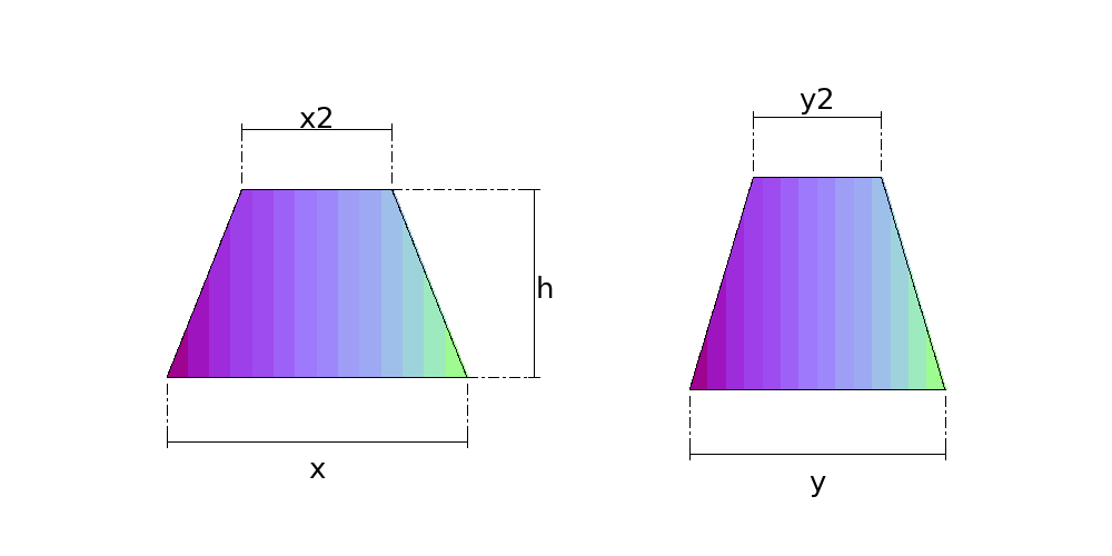
The pyramid frustum: the reducer between two rectangular openings, on the same axis. It is the only transition in this catalogue that is not triangulated, and does not need to be — each of the four faces has its bottom edge parallel to its top one, so the face is a flat trapezoid and its pattern is the face itself, with no approximation.
Where it is used
Reducers in exhaust and air-conditioning ductwork, hoppers and silo outlets, feed chutes, transitions between rectangular-section equipment.
Measurements the calculation needs
- X Side X of the bottom mouth
- Y Side Y of the bottom mouth
- X2 Side X of the top mouth
- Y2 Side Y of the top mouth
- H Height between the mouths
- THK Plate thickness
- R Bend radius
How it develops: the formulas
- Slant height of each pair of faces
hx = √( h² + ((Y − Y2)/2)² ) ; hy = √( h² + ((X − X2)/2)² )hx is for the face with X at the bottom (it steps back (Y − Y2)/2) and hy for the face with Y. In the example (800 × 600 to 400 × 300, h = 500): hx = 522.0 mm and hy = 538.5 mm.- Each face
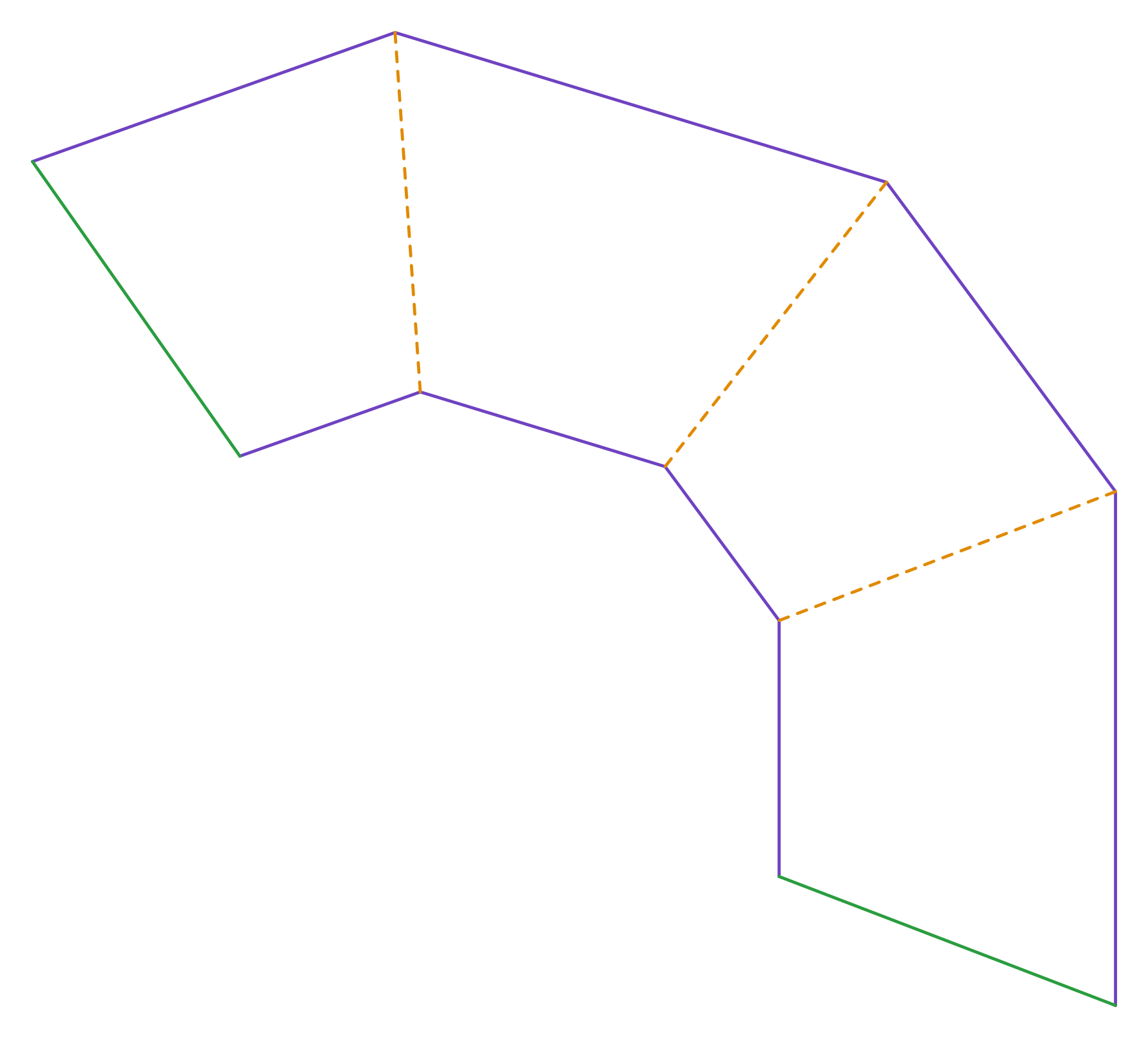
trapezoid of bases X and X2 (or Y and Y2) and height hx (or hy)All four faces are flat: the bottom edge is parallel to the top one. The template is exact, with no triangulation.- Angle between neighbouring faces
the dihedral comes from the 3D modelIn the example it is 96.1°: the angle measured with a protractor on the finished part, and the one the assembly note gives.
Worked example
The values the form comes pre-filled with, run through the tool itself:
| Side X of the bottom mouth | 800 mm |
|---|---|
| Side Y of the bottom mouth | 600 mm |
| Side X of the top mouth | 400 mm |
| Side Y of the top mouth | 300 mm |
| Height between the mouths | 500 mm |
| Plate thickness | 3 mm |
| Bend radius | 0 mm |
| The flat pattern fits a plate of | 1681 × 1509 mm |
Result of the example
| Plate | 1681 × 1509 mm |
|---|
Assembly notes
The pattern develops the SHARP CORNER, on the mean line — the theoretical layout, which is what gets delivered. If you fold it on a press brake with an inside radius, the blank comes out LONG: each fold needs the deduction 2*(r+t)*tan(a/2) − a*(r + k*t), with r the inside radius, a the bend angle in radians, and your tooling's k. On a 500x300 tube in 1.5 mm sheet with four 90° folds that is 3.5 mm at radius 0.75 and 9.0 mm at radius 4.5 — always to be taken off. A welded corner from separate plates needs no deduction at all.
Fold to an angle of 96.1° BETWEEN THE TWO FACES — what a protractor reads on the finished part, not the press stroke angle. Every crease on this part has the same angle.
How to mark it out on the plate
- Work out hx and hy. Mark the four faces in sequence, joined along the sloping edges, with the seam in the middle of a face or on an edge.
- On each face mark the base (X or Y), go up hx or hy on the axis of symmetry and mark the smaller opening (X2 or Y2) centred.
- Crease along the edges and fold to the angle between faces, checked with a protractor; the part closes with one seam.
Common mistakes and tolerances
- Using one slant height on all four faces
- They only coincide when the reduction is equal in X and Y. In the example hx and hy differ by 16.5 mm.
- Folding with a radius and not deducting
- The template is the sharp corner on the mean surface. Each fold with an inside radius needs the deduction 2 × (r + t) × tan(a/2) − a × (r + k × t); the assembly note gives the figure when r is entered.
Frequently asked questions
- Why is this part not triangulated like the rectangle-to-round?
- Because all four faces are flat. Two parallel lines always lie in one plane, and here the bottom edge of each face is parallel to its top edge — so there is no curved surface to approximate with triangles. On the rectangle-to-round one opening is a circle, and then no face is flat at all.
- Is the slant height the same on all four faces?
- No, and that is exactly where marking out from memory goes wrong. The face with X at the bottom steps back (Y − Y2)/2 and the face with Y steps back (X − X2)/2, so each pair has its own slant height. They only coincide when the reduction is equal in both directions.
- Can the top opening be larger than the bottom one?
- Yes, and in one direction only if you like — widening in X while narrowing in Y is routine in ductwork. The calculation does not distinguish a reducer from an expander.
- What if both openings are the same?
- You get a straight rectangular tube, and the pattern is a plain rectangle of perimeter by height. That is a real part, not a degenerate case, and the calculation accepts it.
An account is required. The free tier covers 20 calculations a month.