Discharge Chute development
What it is
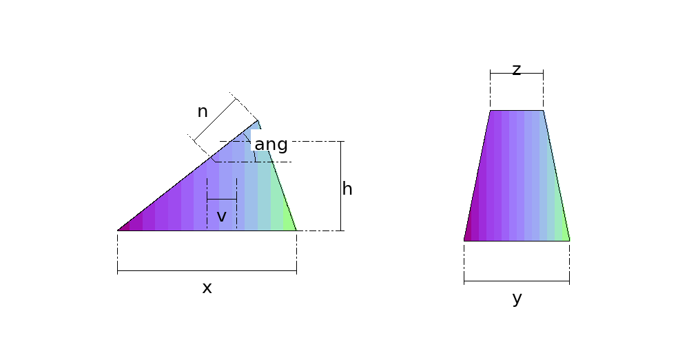
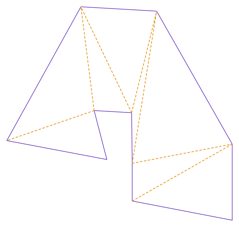
A rectangular hopper with its outlet tilted and off centre — the spout the material drops through onto whatever carries it next. Because the outlet is tilted, the four faces are no longer flat: the bottom edge of each is not parallel to its top edge, the quadrilateral is skew, and the pattern comes out by triangulation.
Where it is used
Silo and bin discharge, transfer between conveyors, crusher and screen spouts, mixer feed.
Measurements the calculation needs
- X Length of the base (the tilt side)
- Y Width of the base
- N Length of the outlet (measured on the tilt)
- Z Width of the outlet
- V Offset of the outlet from centre
- ANG Tilt of the outlet
- H Height to the centre of the outlet
- THK Plate thickness
Worked example
The values the form comes pre-filled with, run through the tool itself:
| Length of the base (the tilt side) | 600 mm |
|---|---|
| Width of the base | 300 mm |
| Length of the outlet (measured on the tilt) | 200 mm |
| Width of the outlet | 150 mm |
| Offset of the outlet from centre | 100 mm |
| Tilt of the outlet | 45° |
| Height to the centre of the outlet | 300 mm |
| Plate thickness | 3 mm |
| The flat pattern fits a plate of | 883 × 833 mm |
Result of the example
| Plate | 883 × 833 mm |
|---|
Assembly notes
The pattern develops the SHARP CORNER, on the mean line — the theoretical layout, which is what gets delivered. If you fold it on a press brake with an inside radius, the blank comes out LONG: each fold needs the deduction 2*(r+t)*tan(a/2) − a*(r + k*t), with r the inside radius, a the bend angle in radians, and your tooling's k. On a 500x300 tube in 1.5 mm sheet with four 90° folds that is 3.5 mm at radius 0.75 and 9.0 mm at radius 4.5 — always to be taken off. A welded corner from separate plates needs no deduction at all.
The angle between faces VARIES from crease to crease on this part, and along each one: the mouth is not parallel to the base, so none of the walls is flat. Check it on the 3D model, crease by crease, and form to fit.
Frequently asked questions
- Where is the height measured to?
- To the CENTRE of the outlet, not to its high edge. The outlet tilts about its centre, so it is the centre that sits at the height given and the two edges rise and fall around it — the same convention as the inclined square-to-round.
- Is the outlet length measured horizontally?
- No, it is measured ALONG the tilted outlet, which is where it exists. Horizontally it projects less — the length times the cosine of the angle — and that projection is what the calculation uses to know whether the outlet still fits within the base's footprint.
- Can the outlet cross the edge of the base?
- No. Past it the rear faces would fold into themselves: there would be no part left, and the pattern would measure more material than the part has. The calculation refuses it.
- And with the angle at zero?
- The outlet comes square and the part becomes an offset pyramid frustum, with all four faces flat again. The calculation accepts it, and at zero offset too the pattern matches the rectangular transition in this same catalogue exactly.