Sheet metal bending calculator: bent profile
What it is
A bent profile is sheet that the press brake turns into a section: the angle, the U channel, the lipped C channel, the Z and the hat (omega), the cold-formed shapes that become purlins, girts, studs, tracks, trims and light framing. The page calculates the blank, the width of the strip before bending, from the K-factor: each bend uses less sheet along the neutral axis than the sum of the outside dimensions, and that bend deduction is what makes the profile come out to size. The drawing puts the bend lines in the middle of each bend zone, with the distance from one to the next.
Where it is used
Roof and wall purlins and girts (lipped C and Z), steel-framing studs and tracks, trim and reinforcing angles, hat channels for cladding and ceilings, door frames, formed gutters and flashings, and any custom section the shop bends on the press brake.
Measurements the calculation needs
- PF Profile type
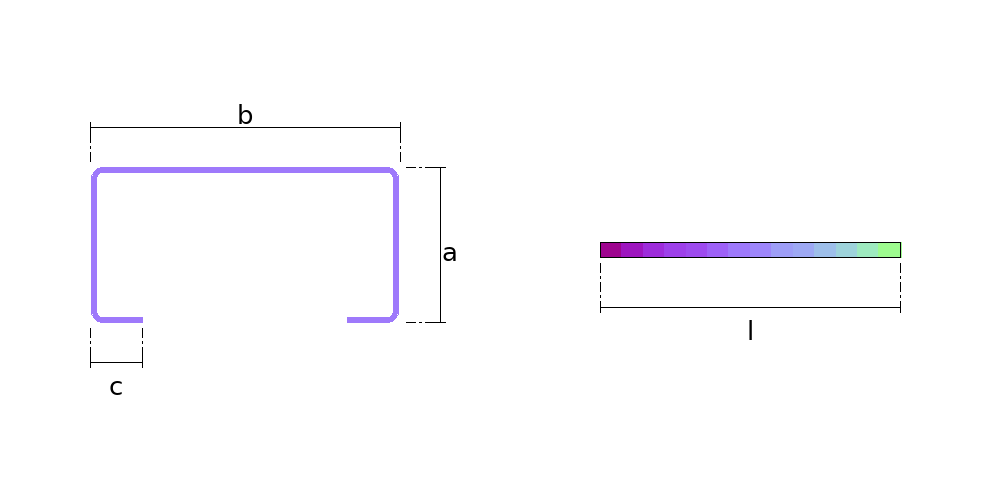
- A Flange (on the hat, the height)
- B Web (on the angle, the other flange)
- C Lip (on the hat, the outer flange; 0 = none)
- ANG Angle between faces
- L Length of the profile
- THK Thickness
- R Inside bend radius (0 = sharp corner)
- KF K-factor (0 = from the table)
Calculate with your own measurements
No account needed: enter the measurements in millimetres or inches and get the figures and the drawing. The scaled PDF template, the DXF for the cutting table and the 3D model take a free account.
Diameters and sides are outside measurements. The flat pattern already allows for the plate thickness, working on the mean line.
Inches or millimetres? mm inches
How it develops: the formulas
- The setback of each bend
OSSB = (r + t) × tan(θ/2) ; θ = 180° − angle between facesFrom the outside virtual sharp to where the arc starts, on each flange. In the example, (2 + 2) × tan 45° = 4 mm.- The arc on the neutral axis
BA = θ × (r + K × t)θ in radians. With r/t = 1 Mario Rossi's table gives K = 0.421: BA = 1.5708 × (2 + 0.842) = 4.46 mm.- The bend deduction and the blank
BD = 2 × OSSB − BA ; L = Σ flanges − n × BDIn the example, BD = 8 − 4.46 = 3.54 mm, and the blank of the 100 × 50 × 17 lipped channel is 17 + 50 + 100 + 50 + 17 − 4 × 3.54 = 219.86 mm.- Where each bend line goes
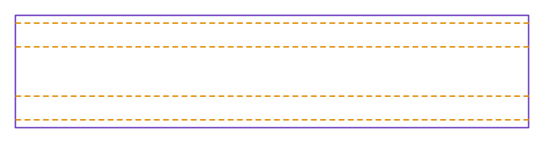
x = flats before + arcs before + BA/2The flat of each flange is its dimension minus one setback per bend at its ends: 13, 42, 92, 42 and 13 mm in the example. The first line is at 13 + 2.23 = 15.23 mm.
Worked example
The values the form comes pre-filled with, run through the tool itself:
| Profile type | Channel, plain or lipped (U, C) |
|---|---|
| Flange (on the hat, the height) | 50 mm |
| Web (on the angle, the other flange) | 100 mm |
| Lip (on the hat, the outer flange; 0 = none) | 17 mm |
| Angle between faces | 90° |
| Length of the profile | 1000 mm |
| Thickness | 2 mm |
| Inside bend radius (0 = sharp corner) | 2 mm |
| K-factor (0 = from the table) | 0 |
| The flat pattern fits a plate of | 1000 × 220 mm |
Result of the example
| Plate | 1000 × 220 mm |
|---|---|
| Area and weight | 0.22 m² · ≈ 3.5 kg in 2 mm steel |
Assembly notes
The blank is 219.9 mm wide, by the length of the profile. Each bend line marks the middle of the bend zone, where the punch lines up.
Bend lines at 15.23, 61.7, 158.16, and 204.62 mm from the end of the first flange: measure from there with a tape, or set the back gauge from it.
Press-brake bend with a K-factor of 42.1% of the thickness: each bend uses 4.5 mm of sheet along the neutral-axis arc and takes 3.5 mm off the sum of the outside dimensions, with a setback of 4 mm on each side of the virtual sharp. The K-factor changes with tooling and material: check it with a test bend on your machine.
The lips bend the same way as the flanges, turning back into the channel: all four bends go the same way.
Fold to an angle of 90° BETWEEN THE TWO FACES — what a protractor reads on the finished part, not the press stroke angle. Every crease on this part has the same angle.
How to mark it out on the plate
- Pick the profile type and enter the flanges measured outside, the angle between faces, the length, the thickness, the inside bend radius and, if you know it, your press brake's K-factor.
- Cut the blank to the calculated width and to the length of the profile.
- Mark the bend lines from the assembly note, measuring from the end of the first flange, or set the back gauge from them.
- Bend each line with the punch on it, in the direction the assembly note gives, to the angle between faces.
- Check the flanges outside with a tape; if they all come out long or all short, adjust the K-factor from that test bend.
Common mistakes and tolerances
- Adding up the outside dimensions and cutting
- The blank comes out long: in 2 mm sheet with a 2 mm radius each 90° bend uses 3.54 mm less than the sum of the outside dimensions. On a four-bend lipped channel, 14 mm.
- Using the wrong radius
- The deduction depends on the radius the bend leaves in the sheet, not on the punch tip radius: in air bending the V opening sets it. Bend an offcut and measure.
- Mixing inside and outside dimensions
- All flanges are outside, to the virtual sharp. The web of a 2 mm channel measured inside is 4 mm smaller, and the whole profile comes out narrow.
Frequently asked questions
- How do you calculate the flat length of a bent part?
- Add the outside dimensions of the flanges and take off the bend deduction of each bend: BD = 2 × (r + t) × tan(θ/2) − θ × (r + K × t), with r the inside radius, t the thickness, θ how far the sheet turns and K the position of the neutral axis. For a lipped channel 100 × 50 × 17 in 2 mm sheet with a 2 mm radius, each bend deducts 3.54 mm, and the blank is 234 − 4 × 3.54 = 219.86 mm.
- What is the K-factor?
- It is where the neutral axis sits, the layer of the sheet that neither stretches nor shrinks in the bend, as a fraction of the thickness from the inside face. It depends on the ratio r/t: the page uses Mario Rossi's table, from 0.35 for a tight bend to 0.5 for an open one, and 0.42 when the radius equals the thickness. If you know your press brake's K-factor, type it in the K-factor field.
- What bend radius should I use?
- The inside radius your tooling leaves in the sheet. In air bending it comes out near 15% of the V opening: with a V of 8 times the thickness, roughly the thickness itself. When in doubt, bend an offcut, measure the radius and the flanges, and check the blank against the page.
- Are the dimensions outside or inside?
- Outside, to the virtual sharp: each flange runs to where the outside faces would meet if the bend were sharp. That is how profiles are dimensioned: the web of a channel is the overall width, and on the Z and the hat the web and the sides run from outside face to outside face.
- Where do the bend lines go?
- In the middle of each bend zone, where the punch lines up. The assembly note gives the distance from each line to the end of the first flange, which is what you mark on the sheet or set on the back gauge: 15.23, 61.7, 158.16 and 204.62 mm in the example.
- What about a zero radius?
- Zero radius is the sharp corner on the mid-plane, for a welded or notched corner: each 90° bend takes one thickness off the blank. It is not the limit of a press-brake bend, because with a small radius the sheet still uses 0.35 of the thickness in the arc; that is why the page asks for the radius when the part goes to the press brake.
You can work out the figures right here, with no account. PDF, DXF, 3D and history take an account — free, with unlimited calculations.