Rectangular Transition flat pattern
What it is
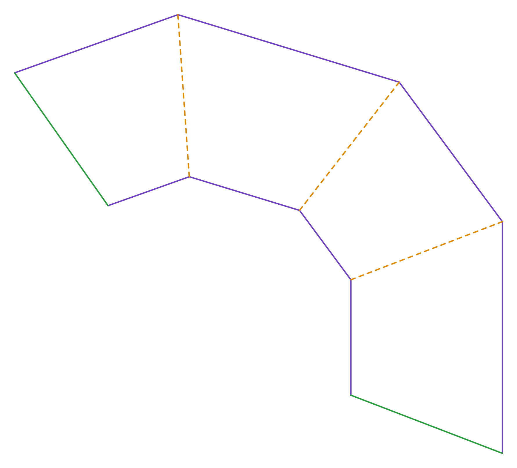
The pyramid frustum: the reducer between two rectangular openings, on the same axis. It is the only transition in this catalogue that is not triangulated, and does not need to be — each of the four faces has its bottom edge parallel to its top one, so the face is a flat trapezoid and its pattern is the face itself, with no approximation.
Where it is used
Reducers in exhaust and air-conditioning ductwork, hoppers and silo outlets, feed chutes, transitions between rectangular-section equipment.
Measurements the calculation needs
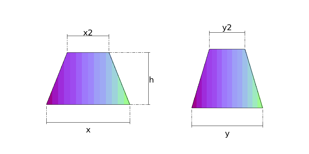
- X Side X of the bottom mouth
- Y Side Y of the bottom mouth
- X2 Side X of the top mouth
- Y2 Side Y of the top mouth
- H Height between the mouths
- THK Plate thickness
- R Bend radius
- NP Number of sheets
- SB Pittsburgh pocket allowance
- SA Pittsburgh flange allowance
- SP End allowance (TDC, S and drive)
Calculate with your own measurements
No account needed: enter the measurements in millimetres or inches and get the figures and the drawing. The scaled PDF template, the DXF for the cutting table and the 3D model take a free account.
Diameters and sides are outside measurements. The flat pattern already allows for the plate thickness, working on the mean line.
Inches or millimetres? mm inches
How it develops: the formulas
- Slant height of each pair of faces
hx = √( h² + ((Y − Y2)/2)² ) ; hy = √( h² + ((X − X2)/2)² )hx is for the face with X at the bottom (it steps back (Y − Y2)/2) and hy for the face with Y. In the example (800 × 600 to 400 × 300, h = 500): hx = 522.0 mm and hy = 538.5 mm.- Each face
trapezoid of bases X and X2 (or Y and Y2) and height hx (or hy)All four faces are flat: the bottom edge is parallel to the top one. The template is exact, with no triangulation.- Angle between neighbouring faces
the dihedral comes from the 3D modelIn the example it is 96.1°: the angle measured with a protractor on the finished part, and the one the assembly note gives.
Worked example
The values the form comes pre-filled with, run through the tool itself:
| Side X of the bottom mouth | 800 mm |
|---|---|
| Side Y of the bottom mouth | 600 mm |
| Side X of the top mouth | 400 mm |
| Side Y of the top mouth | 300 mm |
| Height between the mouths | 500 mm |
| Plate thickness | 3 mm |
| Bend radius | 0 mm |
| Number of sheets | One sheet (the whole piece) |
| Pittsburgh pocket allowance | 0 mm |
| Pittsburgh flange allowance | 0 mm |
| End allowance (TDC, S and drive) | 0 mm |
| The flat pattern fits a plate of | 1681 × 1509 mm |
Result of the example
| Plate | 1681 × 1509 mm |
|---|---|
| Area and weight | 1.11 m² · ≈ 26.0 kg in 3 mm steel |
Assembly notes
The pattern develops the SHARP CORNER, on the mean line — the theoretical layout, which is what gets delivered. If you fold it on a press brake with an inside radius, the blank comes out LONG: each fold needs, against this pattern, the deduction 2*(r+t/2)*tan(a/2) − a*(r + k*t), with r the inside radius, a the bend angle in radians, and your tooling's k. On a 500x300 tube in 1.5 mm sheet with four 90° folds that is 3.6 mm at radius 0.75 and 9.3 mm at radius 4.5 — always to be taken off. A welded or V-notched corner closes on the sharp corner and needs no deduction.
Fold to an angle of 96.1° BETWEEN THE TWO FACES — what a protractor reads on the finished part, not the press stroke angle. Every crease on this part has the same angle.
How to mark it out on the plate
- Work out hx and hy. Mark the four faces in sequence, joined along the sloping edges, with the seam in the middle of a face or on an edge.
- On each face mark the base (X or Y), go up hx or hy on the axis of symmetry and mark the smaller opening (X2 or Y2) centred.
- Crease along the edges and fold to the angle between faces, checked with a protractor; the part closes with one seam.
Common mistakes and tolerances
- Using one slant height on all four faces
- They only coincide when the reduction is equal in X and Y. In the example hx and hy differ by 16.5 mm.
- Folding with a radius and not deducting
- The template is the sharp corner on the mean surface. Each fold with an inside radius needs the deduction 2 × (r + t/2) × tan(a/2) − a × (r + k × t) against the template; the assembly note gives the figure when r is entered.
Guides about this part
- The neutral axis of plate: why every development uses D − t, and the bend deduction
- Plenum box and plenum transition layout: the sides, the end cap, the collar and the transitions
Frequently asked questions
- Why is this part not triangulated like the rectangle-to-round?
- Because all four faces are flat. Two parallel lines always lie in one plane, and here the bottom edge of each face is parallel to its top edge — so there is no curved surface to approximate with triangles. On the rectangle-to-round one opening is a circle, and then no face is flat at all.
- Is the slant height the same on all four faces?
- No, and that is exactly where marking out from memory goes wrong. The face with X at the bottom steps back (Y − Y2)/2 and the face with Y steps back (X − X2)/2, so each pair has its own slant height. They only coincide when the reduction is equal in both directions.
- Can the top opening be larger than the bottom one?
- Yes, and in one direction only if you like — widening in X while narrowing in Y is routine in ductwork. The calculation does not distinguish a reducer from an expander.
- What if both openings are the same?
- You get a straight rectangular tube, and the pattern is a plain rectangle of perimeter by height. That is a real part, not a degenerate case, and the calculation accepts it.
- Can it come out in two or four sheets?
- Yes, in the Number of sheets field. With two you get two equal L-shaped sheets, each with one X face, one Y face and the fold between them, and the seams on two opposite corners. With four the faces come out apart, two of each pattern, with a seam on all four corners -- the way to go when the piece will not fit the sheet. The assembled piece is the same.
- Does the pattern include the Pittsburgh and TDC allowances?
- It does if you ask: enter the Pittsburgh pocket and flange allowances and the end allowance, and the drawing comes with them, the fold line on the net edge and a notch one thickness wide at the corners. The pocket goes on the face of the short side of the duct, which is where the female Pittsburgh goes. The figures come from your lock former: the Lockformer LK-20 takes 25 mm for the pocket and 6 mm for the flange, and TDC/TDF uses close to 50 mm per end. With everything at zero, the default, the pattern is net.
You can work out the figures right here, with no account. PDF, DXF, 3D and history take an account — free, with unlimited calculations.