Tapered Screw Flight flat pattern
What it is
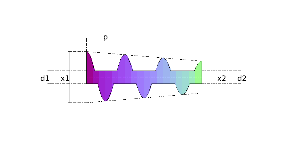
The tapered screw flight is the flight whose diameters change along the shaft: the tapered auger of a feeder screw, which draws evenly from the whole hopper outlet, and the flight on a conical shaft. Every turn has its own diameters and comes out on its own sheet, in fitting order, the way a heavy flight is pressed one pitch at a time. The calculation develops each turn with both edges at the true length of their helix, and returns the sheets drawn in arcs, the 1:1 template and the DXF.
Where it is used
Hopper and bin feeder screws, live-bottom bin unloaders, conical-shaft screws in mixers and presses, and conveyors that taper down to a smaller outlet.
Measurements the calculation needs
- D1 Inside diameter at the start (shaft)
- D2 Inside diameter at the end (shaft)
- X1 Outside diameter at the start
- X2 Outside diameter at the end
- P Pitch (rise per turn)
- NV Number of turns
- THK Plate thickness
Calculate with your own measurements
No account needed: enter the measurements in millimetres or inches and get the figures and the drawing. The scaled PDF template, the DXF for the cutting table and the 3D model take a free account.
Diameters and sides are outside measurements. The flat pattern already allows for the plate thickness, working on the mean line.
Units: mm inches
How it develops: the formulas
- The diameters of each turn
Dk = D1 + (D2 − D1) × k / nk runs from 0 to n, the number of turns; it holds for the outside and the inside diameter. In the example, outside diameter from 400 to 250 over 3 turns: it drops 50 mm a turn, 400 → 350 → 300 → 250, and the shaft stays at 100.- The length of the edges of one turn
L ≈ √( (π × D̄)² + p² + ((Db − Da) / 2)² )D̄ is the mean diameter of the turn, and Da and Db the diameters at its ends. The third term is what the taper adds: the edge also moves in or out. In the example, the outer edge measures 1216.0 mm on the first turn, 1064.6 on the second and 915.0 on the third; the inner one, 434.4 mm on all of them. The calculation integrates the helix instead of using the mean.- The opening of the sheet
sin(δ/2) = (b − a) / (w1 + w2)For each piece of the turn, a and b are the inner and outer chords of the helix, and w1 and w2 the width of the flight at the two ends of the piece. The formula is the one for constant width; with the width changing, δ comes out of a quadratic. The δ add up to the opening of the sheet, and with constant diameters the sheet is the sector of the helicoid.
Worked example
The values the form comes pre-filled with, run through the tool itself:
| Inside diameter at the start (shaft) | 3-15/16" (3.937) |
|---|---|
| Inside diameter at the end (shaft) | 3-15/16" (3.937) |
| Outside diameter at the start | 15-3/4" (15.748) |
| Outside diameter at the end | 9-13/16" (9.8425) |
| Pitch (rise per turn) | 11-13/16" (11.811) |
| Number of turns | 3 |
| Plate thickness | 1/4" (0.2362) |
| The flat pattern fits a plate of | 17-1/4" × 16-3/4" |
| Flat patterns produced | 3 |
Result of the example
| Plate 1 | 17-1/4" × 16-3/4" |
|---|---|
| Area and weight | 1.2 ft² · ≈ 11.8 lb in 1/4" steel |
| Edges | inner 17-1/8" · outer 47-7/8" |
| Plate 2 | 15-3/8" × 14-7/8" |
| Area and weight | 0.91 ft² · ≈ 8.8 lb in 1/4" steel |
| Edges | inner 17-1/8" · outer 41-15/16" |
| Plate 3 | 13-1/2" × 13" |
| Area and weight | 0.64 ft² · ≈ 6.1 lb in 1/4" steel |
| Edges | inner 17-1/8" · outer 36" |

Assembly notes
The flight is NOT developable: a helicoid has negative Gaussian curvature, and no flat plate seats on it without stretching. This is the classic development, and what it gets exactly right are the two EDGES -- each measures the true length of its own helix, and that is what the bench checks. Its AREA is 1.8% over at these dimensions, and that surplus is what forming absorbs as the blank is opened and pulled to pitch. A blank larger than the finished flight is expected, not an error.
Each turn comes out on its own sheet, and the 3 sheets are all different: sheet 1 is the turn at the start, with the diameters of the first end, and the last one is the turn at the far end. Number each sheet as you cut it, mark its start and finish ends, and fit the turns on the shaft in that order, the finish end of one against the start end of the next.
How to mark it out on the plate
- Enter the inside and outside diameters at both ends, the pitch and the number of turns. Each turn comes out on its own sheet, numbered from the start end to the far end.
- Cut each sheet and mark on it the number of the turn and its start and finish ends.
- Check the edges of each sheet before forming: the inner and the outer edge must measure what the calculation gives for that turn.
- Open each sheet and pull the ends apart until they are one pitch apart, measured along the shaft.
- Fit the turns on the shaft in order, the finish end of one against the start end of the next, and weld the inner edge to the shaft and the joint between turns.
Common mistakes and tolerances
- Fitting the turns out of order
- Every turn has its own diameters. Swapping two leaves a step in the outer edge, and the screw no longer tapers evenly.
- Using the plain helicoid template at the mean diameter
- One diameter for the whole turn gets both ends wrong: in the example, the first turn runs from 400 to 350 mm, and a 375 template leaves the edge 12.5 mm in at one end and out at the other.
- Expecting the flat sheet to sit without stretching
- Like the plain helicoid, the tapered one is not developable. The template gets the edges right; the area is 1.8% over on the first turn of the example, and forming absorbs it.
Guides about this part
Frequently asked questions
- Why does each turn come out on its own sheet?
- Because the diameters change along the shaft, and every turn has its own. In the example, outside diameter from 400 to 250 mm over 3 turns, the first turn runs from 400 to 350, the second from 350 to 300 and the third from 300 to 250; the sheets measure 439 × 426, 391 × 378 and 343 × 330 mm and come out numbered in fitting order.
- How do I work out the length of the edges of each turn?
- From the conical helix: L ≈ √((π × D̄)² + p² + ((Db − Da)/2)²), with D̄ the mean diameter of the turn and Da and Db the diameters at its ends. In the example, the outer edge of the first turn measures 1216.0 mm and the inner one 434.4 mm. The calculation integrates the helix point by point instead of using the mean.
- Does it work for a conical shaft?
- It does. Different inside diameters at the two ends describe a conical shaft; equal ones, the straight shaft of a tapered feeder screw. The outside diameter can grow instead of shrinking, too.
- How many turns are there in a metre of flight?
- A thousand divided by the pitch: with a 300 mm pitch, 3.33 turns per metre. Here the number of turns is whole, because each turn is a sheet; adjust the length or the pitch to make it come out even.
You can work out the figures right here, with no account. PDF, DXF, 3D and history take an account — free, with unlimited calculations.