Parallel-Axis Nozzle on a Cone development
What it is
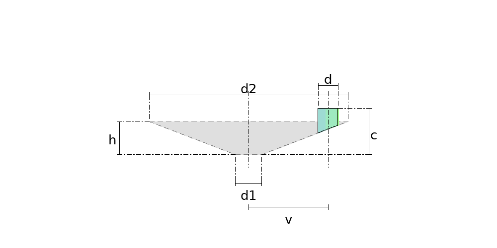
The upright nozzle on a hopper, a conical silo or a tank's conical roof: its axis runs PARALLEL to the cone's, offset by v, rather than crossing it as in the ordinary cone branch.
Where it is used
Hoppers and bins in agriculture and mining, cyclone bodies, conical tank roofs, conical silos, any nozzle that has to stand plumb so the flange comes out level.
Measurements the calculation needs
- D1 Diameter of the smaller mouth (base)
- D2 Diameter of the larger mouth (top)
- H Height of the cone
- D Diameter of the nozzle
- V Distance between the axes
- C Length of the nozzle (from the cone base)
- DV Divisions
- THK Plate thickness
Worked example
The values the form comes pre-filled with, run through the tool itself:
| Diameter of the smaller mouth (base) | 400 mm |
|---|---|
| Diameter of the larger mouth (top) | 3000 mm |
| Height of the cone | 500 mm |
| Diameter of the nozzle | 300 mm |
| Distance between the axes | 1200 mm |
| Length of the nozzle (from the cone base) | 700 mm |
| Divisions | 16 |
| Plate thickness | 6 mm |
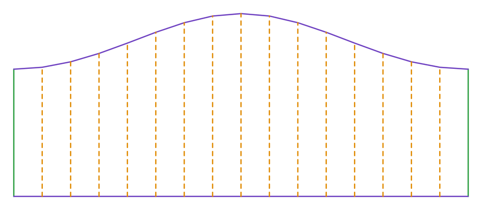
| The flat pattern fits a plate of | 924 × 372 mm |
Result of the example
| Plate | 924 × 372 mm |
|---|
Frequently asked questions
- How is this different from the ordinary cone branch?
- In the ordinary one the branch axis CROSSES the cone axis — that is the horizontal branch. Here it runs parallel, offset by v. On a hopper and on a conical roof the nozzle is mounted plumb, so the flange is level and the product does not pool, and the cut curve is a different one.
- Where do I measure the length c from?
- From the cone's BASE PLANE to the tip of the nozzle. That differs from the ordinary cone branch, where c is measured from the cone's axis — there the branch crosses the axis and that is the only datum that works; here the nozzle never goes near it, and the base plane is what you have on the bench.
- Why can't the nozzle sit close to the axis?
- Because the inner generators would pass through the small mouth and meet no cone at all — their cut would fall below the base, where the part does not exist. The guard asks v to exceed d/2 plus d1/2, and the same applies on the other side against the large mouth. That is geometry, not caution.
- Is the calculation exact or approximate?
- Exact, and it is the simplest intersection in this catalogue. Every generator of the nozzle is a vertical line, so it stays at a constant distance from the cone's axis, and the point at rho from the axis meets the cone at rho/tan(a). No quartic, no root to choose, no approximation anywhere.
- What about the hole in the cone?
- That is the companion part, "Cone with Parallel-Axis Nozzle Hole". Enter the same figures in both and the two patterns match, because the intersection is worked out once, in one place in the code.
Calculate a Parallel-Axis Nozzle on a Cone
An account is required. The free tier covers 20 calculations a month.