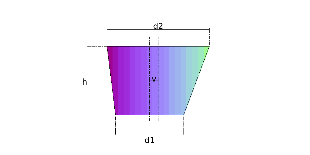
Offset Cone development
What it is
The offset cone is the reducer whose two mouths are parallel but not coaxial: the top one is shifted by an amount you enter. At zero offset it is the concentric reducer; at the offset where both mouths become tangent on the same side, it is the eccentric reducer with one side plumb; and beyond that it is what the shop calls an external eccentric, with the top mouth outside the footprint of the bottom one.
Where it is used
Axis offsets in pipework where the reducer also has to shift the line, transitions between misaligned nozzles, connections that clear a beam or a piece of equipment, hopper bottoms with the outlet off centre.
Measurements the calculation needs
- D1 Diameter of the bottom mouth
- D2 Diameter of the top mouth
- H Vertical height between the mouths
- V Offset between the axes
- DV Divisions
- THK Plate thickness
Worked example
The values the form comes pre-filled with, run through the tool itself:
| Diameter of the bottom mouth | 800 mm |
|---|---|
| Diameter of the top mouth | 1200 mm |
| Vertical height between the mouths | 800 mm |
| Offset between the axes | 100 mm |
| Divisions | 16 |
| Plate thickness | 3 mm |
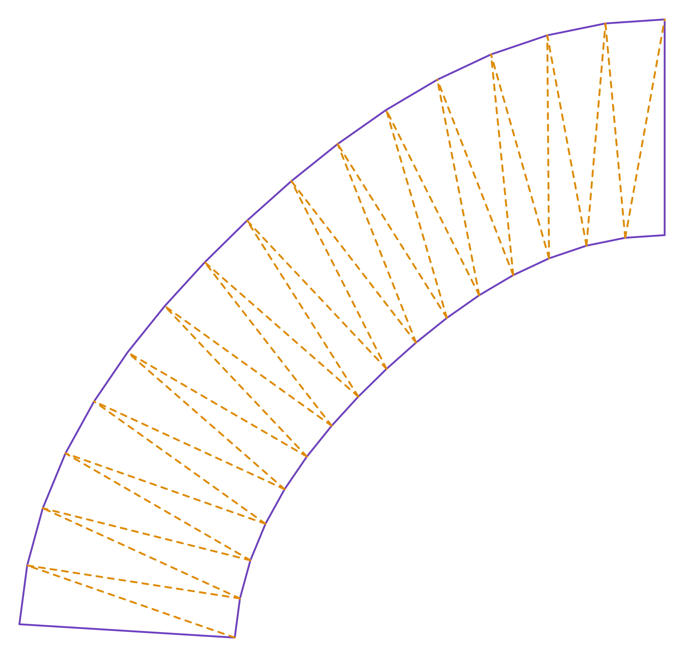
| The flat pattern fits a plate of | 2555 × 2449 mm |
Result of the example
| Plate | 2555 × 2449 mm |
|---|
Guides about this part
Frequently asked questions
- How is this different from the oblique cone already in the catalogue?
- It is not, when the offset is exactly the difference between the two radii. The oblique cone is this same cone with the offset locked at that value, which is what leaves one generatrix vertical. Here the offset is yours, so one page covers the concentric case, the tangent one and everything between.
- Why is the flat pattern triangulated rather than a compass sector?
- Because only the concentric cone is a right circular cone, and only it opens into a sector of a circular ring. Shift one mouth and the generatrices stop converging on a point, so the only exact layout is to join the two mouths with true-length triangles. The pattern stays exact; what changes is the method.
- Can the offset go past the point where the mouths become tangent?
- It can, and that is a catalogue part in its own right. Past the tangent the top mouth leaves the footprint of the bottom one, the part stops having a plumb side and starts leaning both ways. The calculation is the same.