350A JIS 10K flange: dimensions, bolt circle and drilling (JIS B 2220)
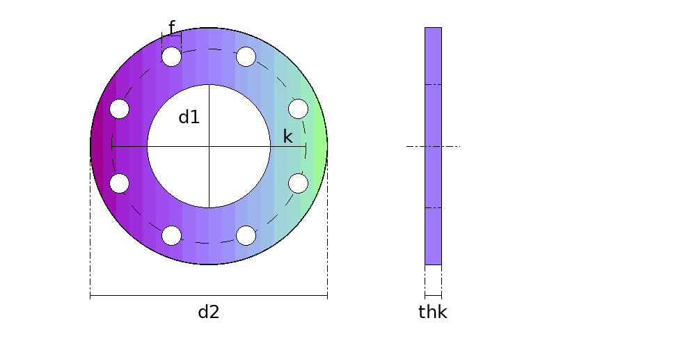
The 350A JIS 10K flange to JIS B 2220 is 490 mm (19.29 in) across, with 16 holes of 25 mm (0.98 in) on a 445 mm (17.52 in) bolt circle, for M22 bolts; the pipe is 355.6 mm (14 in) outside. The holes straddle the centre lines, the first one 11.25° off, and the chord between neighbouring holes, which is the divider setting for stepping the drilling out, is 86.8 mm (3.42 in).
Download the 1:1 drilling template (free PDF) Open in the generator: DXF for plasma and laser
On A4 or Letter sheets to tape together, with a check ruler on every sheet: print at actual size, 100 %. No account needed.
Dimensions
| Outside diameter | 490 mm (19.29 in) |
|---|---|
| Flange thickness (t) | 26 mm (1.02 in) |
| Bolt circle (PCD) | 445 mm (17.52 in) |
| Number of holes | 16 |
| Hole diameter | 25 mm (0.98 in) |
| Bolts | M22 |
| Pipe outside diameter | 355.6 mm (14 in) |
| Angle between holes | 22.5° |
| First hole from the centre line | 11.25° |
| Chord between neighbouring holes | 86.8 mm (3.42 in) |
The thickness of the steel flange in JIS B 2220; cast iron flanges are thicker. The bolts are metric, M22, and their length depends on the gasket and the type of flange.
Hole coordinates
From the centre of the flange, in mm, with the first hole 11.25° off the horizontal axis and the others counter-clockwise, as the standards lay the drilling out.
| Hole | Angle | x (mm) | y (mm) |
|---|---|---|---|
| 1 | 11.25° | 217.7 | 43.3 |
| 2 | 33.75° | 184.6 | 123.3 |
| 3 | 56.25° | 123.3 | 184.6 |
| 4 | 78.75° | 43.3 | 217.7 |
| 5 | 101.25° | -43.3 | 217.7 |
| 6 | 123.75° | -123.3 | 184.6 |
| 7 | 146.25° | -184.6 | 123.3 |
| 8 | 168.75° | -217.7 | 43.3 |
| 9 | 191.25° | -217.7 | -43.3 |
| 10 | 213.75° | -184.6 | -123.3 |
| 11 | 236.25° | -123.3 | -184.6 |
| 12 | 258.75° | -43.3 | -217.7 |
| 13 | 281.25° | 43.3 | -217.7 |
| 14 | 303.75° | 123.3 | -184.6 |
| 15 | 326.25° | 184.6 | -123.3 |
| 16 | 348.75° | 217.7 | -43.3 |
Bolt tightening order
1 – 9 – 5 – 13 → 3 – 11 – 7 – 15 → 2 – 10 – 6 – 14 → 4 – 12 – 8 – 16
The cross pattern of ASME PCC-1, with the holes numbered as in the table above, so that the gasket is pulled down evenly. Go round in at least three passes, raising the torque each time (about 30 %, 60 % and 100 %), then go round in order until no nut turns. The torque itself depends on the bolt, the gasket and the lubricant: it comes from the gasket or bolt supplier.
Questions
- How many bolts does a 350A JIS 10K flange have?
- 16, of M22, through holes of 25 mm (0.98 in) on a 445 mm (17.52 in) bolt circle.
- What is the bolt circle of a 350A JIS 10K flange?
- 445 mm (17.52 in). The holes are 22.5° apart, and the first one sits 11.25° off the centre line, so that two flanges mate in any symmetric position. The chord between neighbouring holes is 86.8 mm (3.42 in).
- Can a 350A JIS 10K flange be cut from plate?
- As a plate flange, for low pressure: ducts, tanks, water lines. The outline and the drilling above are what the flange calculator draws, with the 1:1 template and the DXF for plasma or laser. For pressure service, the flange takes the material, thickness and facing that JIS B 2220 sets for its class.
- In what order are the bolts of a 350A JIS 10K flange tightened?
- In a cross pattern, with the holes numbered round the flange: 1, 9, 5, 13, 3, 11, 7, 15, 2, 10, 6, 14, 4, 12, 8, 16. In at least three passes, raising the torque each time, and then round in order until no nut turns.
Draw a flange
The same pipe in other standards
- NPS 14 class 150
- NPS 14 class 300
- NPS 14 class 600
- DN 350 PN 10
- DN 350 PN 16
- DN 350 PN 25
- DN 350 PN 40
Guides on the flange
- Bolt circle layout: the position of each hole, the chord between holes and a chord chart
- Laser and plasma cutting cost calculator: the formula, a worked example and how to measure the cut length