Spur gear generator
1:1 template and DXF
What it is
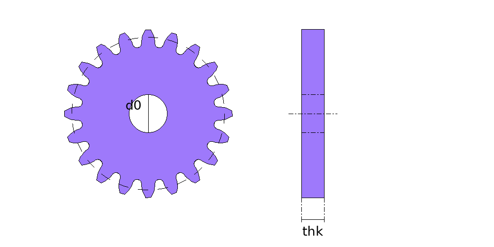
The spur gear cut from flat plate, for laser, plasma or waterjet. The calculation generates the tooth the way a hob does: the basic rack rolls on the pitch circle, and the plate keeps whatever it does not touch -- the involute flank, the root fillet and, on small tooth counts, the undercut that a real gear has. It returns the pitch, outside, root and base diameters, the span measurement to check with a caliper, the full-size template and a DXF drawn in arcs. The tooth size goes in module or diametral pitch (DP), at 20°, 25° or 14.5°.
Where it is used
Drives for machines built in the shop, motor reductions, replacement gears for farm and old machinery that can no longer be bought, sliding gate pinions, prototypes, models and robotics, and the gears a plasma table or router cuts for itself.
Measurements the calculation needs
- ND Number of teeth
- MP Module (mm) or DP
- TP Tooth size given as
- AP Pressure angle
- XD Profile shift (x, in modules)
- D0 Bore (0 for no bore)
- THK Plate thickness
Calculate with your own measurements
No account needed: enter the measurements in millimetres or inches and get the figures and the drawing. The scaled PDF template and the 3D model take a free account; the DXF for the cutting table is part of full access.
Inches or millimetres? mm inches
How it develops: the formulas
- Pitch diameter
d = m × zm is the module and z the number of teeth; in diametral pitch, m = 25.4 / DP. In the example, module 2 with 20 teeth: d = 40 mm (1.575 in).- Outside and root diameters
da = d + 2 m (1 + x) ; df = d − 2 m (1.25 − x)x is the profile shift, in modules. The 1.25 is that of the 20° and 25° racks; the 14.5° rack has 1.157. In the example: 44 and 35 mm.- Base diameter
db = d × cos αα is the pressure angle; the involute unwinds from the base circle. In the example, at 20°: db = 37.59 mm.- Tooth thickness on the pitch circle
s = m (π / 2 + 2 x tan α)With no profile shift it is half the pitch: 3.14 mm at module 2.- Span over k teeth
W = m cos α [π (k − 0.5) + z inv α] + 2 x m sin αinv α = tan α − α, with α in radians, and k = z α / 180° + 0.5, rounded. In the example: k = 3 and W = 15.32 mm (0.6032 in).
Worked example
The values the form comes pre-filled with, run through the tool itself:
| Number of teeth | 20 |
|---|---|
| Module (mm) or DP | 2 |
| Tooth size given as | Module (mm) |
| Pressure angle | 20° (today's standard) |
| Profile shift (x, in modules) | 0 |
| Bore (0 for no bore) | 10 mm |
| Plate thickness | 6 mm |
| The flat pattern fits a plate of | 44 × 44 mm |
Result of the example
| Plate | 44 × 44 mm |
|---|---|
| Area and weight | 0.001 m² · ≈ 0.06 kg in 6 mm steel |
| Arc radii | 5 mm · 17.5 mm · 22 mm |
| Sector angle | 360 · 0.7 · 3.6° |

Assembly notes
Module 2 (DP 12.7), 20 teeth, 20° pressure angle: pitch diameter 40 mm, outside diameter 44 mm, root diameter 35 mm and base diameter 37.59 mm.
To check the teeth with a caliper: across 3 teeth, with the flat jaws resting on the flanks, the reading must be 15.32 mm. This is the span measurement (Wildhaber), which does not depend on the outside diameter.
It meshes with another gear of the same module and pressure angle. With no profile shift, the centre distance is the mean of the pitch diameters, m × (z1 + z2) / 2; with profile shift, the two gears are calculated together.
Laser or plasma cut, the gear suits slow and medium-speed drives. The DXF is the part outline, and kerf compensation is left to the machine: check the outside diameter and the span measurement on the first part. The heat warps the plate and pulls the bore off centre: cut the bore undersize and finish it on the lathe with the teeth running true. For backlash, a profile shift of −0.05 thins each tooth by about 0.04 module.
How to mark it out on the plate
- Choose the tooth size in module or DP, the number of teeth and the pressure angle -- the same as the gear this one will mesh with.
- Cut from flat, stress-free plate. Cut the bore first and undersize, so the outline is cut while the part is still held by the sheet.
- Let it cool on the table before moving it: a hot plate pulls out of flat.
- Grip it on the lathe centred on the outside diameter and finish the bore, so that the teeth run true.
- Check the span measurement and the outside diameter, and mount it with its mate at the centre distance, m × (z1 + z2) / 2.
Common mistakes and tolerances
- A different module or pressure angle from the mate
- Two gears only mesh with the same module and the same pressure angle. Module 2.5 does not mesh with 10 DP (module 2.54), and 20° does not mesh with 14.5°.
- The wrong centre distance
- Too far apart, the teeth knock and wear; too close, they bind. With no profile shift the distance is m × (z1 + z2) / 2; with profile shift, the two gears are calculated together.
- Too few teeth with no profile shift
- Below 17 teeth at 20° (32 at 14.5°), the root comes out undercut and the tooth is weak. Use the profile shift the note gives, and correct the mating gear.
- A plasma-cut bore, to size
- A plasma bore comes out tapered and off centre, and a gear that runs out binds. Cut the bore undersize and finish it on the lathe.
Frequently asked questions
- How do you calculate the diameter of a gear?
- The pitch diameter is the module times the number of teeth, d = m × z; the outside diameter adds two modules, da = m × (z + 2); the root diameter takes off two and a half, df = m × (z − 2.5). In the example, module 2 with 20 teeth: 40, 44 and 35 mm. In diametral pitch, d = z / DP in inches, and the module is 25.4 divided by the DP.
- What tooth shape comes out?
- The involute, generated by the ISO 53 rack (profile A) at 20°, or by the AGMA racks at 25° and 14.5°. The flank is the involute of the base circle, the root is the fillet left by the rounded tip of the rack, and below 17 teeth at 20° the rack cuts into the foot of the involute (undercut), just as a hob does. Gears generated this way mesh with any other gear of the same module and pressure angle.
- Can you cut a gear on a laser or a plasma table?
- Yes, for slow and medium-speed drives: gates, farm machinery, motor reductions, models. A laser cuts the tooth as accurately as module 1 (25 DP) already needs; on plasma, keep to module 3 (8 DP) and up. The heat warps the plate and pulls the bore off centre: cut the bore undersize and finish it on the lathe. For fast or heavily loaded drives, a machined and hardened gear.
- How do you check a gear after cutting it?
- With the span measurement (Wildhaber): with the flat jaws of a caliper resting on the flanks of k consecutive teeth, the reading must match the note. In the example, across 3 teeth: 15.32 mm. It does not depend on the outside diameter, which is what the cut gets most wrong.
You can work out the figures right here, with no account. PDF, 3D and history take an account — free, with unlimited calculations. DXF is part of full access.