Tapered Segmented Bend flat pattern
What it is
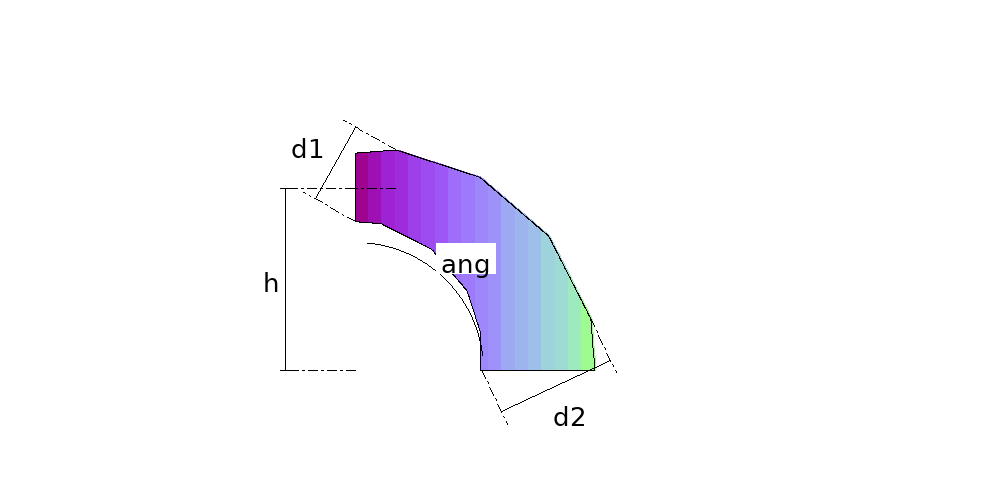
The mitred bend that also reduces: it goes in at one diameter and comes out at another, along the same arc. It is the part nobody wants to mark out by hand, because here the gores are ALL DIFFERENT — s + 1 patterns instead of the two a constant-diameter bend takes.
Where it is used
Flues and extraction ducts that taper as they rise, curved transitions in process piping, dust collection, fan outlets that change size through the bend.
Measurements the calculation needs
- D1 Smaller diameter (inlet mouth)
- D2 Larger diameter (outlet mouth)
- H Bend radius (on the axis)
- ANG Angle of the bend
- S Number of gores
- DV Divisions
- THK Plate thickness
Calculate with your own measurements
No account needed: enter the measurements in millimetres or inches and get the figures and the drawing. The scaled PDF template, the DXF for the cutting table and the 3D model take a free account.
Diameters and sides are outside measurements. The flat pattern already allows for the plate thickness, working on the mean line.
Units: mm inches
Worked example
The values the form comes pre-filled with, run through the tool itself:
| Smaller diameter (inlet mouth) | 11-13/16" (11.811) |
|---|---|
| Larger diameter (outlet mouth) | 19-11/16" (19.685) |
| Bend radius (on the axis) | 31-1/2" (31.4961) |
| Angle of the bend | 90° |
| Number of gores | 4 |
| Divisions | 32 |
| Plate thickness | 1/4" (0.2362) |
| The flat pattern fits a plate of | 58-11/16" × 22-3/4" |
| Flat patterns produced | 5 |
Result of the example
| Plate 1 | 37-1/16" × 14-1/16" |
|---|---|
| Area and weight | 1.5 ft² · ≈ 14.7 lb in 1/4" steel |
| Plate 2 | 42-7/8" × 20-5/16" |
| Area and weight | 3.7 ft² · ≈ 35.4 lb in 1/4" steel |
| Plate 3 | 48-11/16" × 21-9/16" |
| Area and weight | 4.2 ft² · ≈ 40.5 lb in 1/4" steel |
| Plate 4 | 54-1/2" × 22-3/4" |
| Area and weight | 4.7 ft² · ≈ 45.7 lb in 1/4" steel |
| Plate 5 | 58-11/16" × 19-5/16" |
| Area and weight | 2.9 ft² · ≈ 27.9 lb in 1/4" steel |

Assembly notes
The gores are ALL DIFFERENT and go in the order they come out, smallest to largest. Assembled out of order the bend does not close — and there is no way to tell from the patterns, because each one closes on its own.
Every gore comes with its longitudinal seam on the throat, the shortest weld, and the gores go together all the same way round, heel to heel. Do not turn a cut gore half a turn to stagger the seams: its long side goes to the throat and the bend loses angle. To stagger them, mark every second gore from the heel instead — cut the paper template on its middle line and swap the two halves.
Frequently asked questions
- Why is every gore a different pattern?
- Because the diameter grows along the bend. On a constant-diameter bend the middle gores are all alike and come on one sheet cut s − 1 times; here each has its own size. That is why the gore count is capped at twelve — twelve gores is already thirteen sheets.
- Does the assembly order matter?
- Very much. The gores go in the order they come out, smallest to largest. Assembled out of order the bend does not close — and there is no telling from the patterns, because each one closes on its own. The printed sheet carries that warning.
- How is the part built geometrically?
- By inscribed spheres: one sphere at each joint, on the same tangent polygon the ordinary bend uses, with growing radii. Each gore is the frustum of the cone circumscribed about two neighbouring spheres — and it is that construction which makes the joints plane ellipses, which is what lets the mitre close.
- Are the two diameters given the openings?
- They are — circles perpendicular to the axis, which is what you measure and what meets the next pipe. Worth saying because it changes the arithmetic: with that definition the taper enters through the tangent of the cone's angle, not the sine, which is what you get if the diameters are taken at the joints.
- Why does the calculation refuse a bend that looks normal?
- Because the plane of each joint does not pass through the middle of the gore: it moves back towards the apex of the cone. With a very open taper, a short radius or too many gores, the first joint falls behind the inlet mouth and the gore would come out inside out, on a plate that looks right and does not assemble. The calculation checks this on every gore and refuses; use fewer gores or a larger radius.
You can work out the figures right here, with no account. PDF, DXF, 3D and history take an account — free, with unlimited calculations.