Pipe-to-Cone Elbow flat pattern
What it is
The pipe-to-cone elbow, the single-cut reducing elbow, is the bend where one leg is pipe and the other is a cone: it turns and reduces, or turns and opens out, in one go, at the outlet of a fan, a cyclone or a hopper. The cone is a true cone, and the joint is flat because both legs are tangent to the same sphere, centred where the centrelines cross. There are two plates: the cut shell and the cut cone sector.
Where it is used
Fan and extractor outlets that turn and change diameter; cyclone and baghouse inlets and outlets; hopper and silo spouts that change direction; duct and chimney bends that change diameter where a tapered segmented bend will not fit.
Measurements the calculation needs
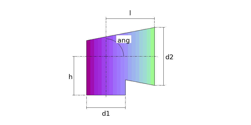
- D1 Pipe diameter
- D2 Cone outlet diameter (outside)
- H From the foot of the pipe to the crossing of the centrelines
- L From the crossing of the centrelines to the cone outlet (on the cone's centreline)
- ANG Bend angle (between the centrelines)
- DV Divisions
- THK Plate thickness
- REF Measured
Calculate with your own measurements
No account needed: enter the measurements in millimetres or inches and get the figures and the drawing. The scaled PDF template, the DXF for the cutting table and the 3D model take a free account.
Diameters and sides outside to outside, inside or on the mean line, as set in “Measured”. The pattern already takes off the thickness, on the mean line.
Inches or millimetres? mm inches
How it develops: the formulas
- The cone apex
(r2² − R²) × p² + 2 × R² × l × p − R² × (l² + r2²) = 0R is the pipe radius, r2 the cone outlet radius and p the distance from the crossing to the apex, along the cone's centreline. The cone touches the sphere of radius R centred at the crossing: sin β = R / |p|. In the example, the apex is 1057.3 mm behind the crossing and β = 10.90°.- The joint
the plane through the meeting points of the inner and outer generatorsIn the plane of the centrelines, the pipe's inner generator meets the cone's inner one, and the outer meets the outer; the joint plane passes through both meeting points. In the example, it cuts the pipe 240.4 mm below the crossing on the inside and 163.9 mm above it on the outside.- The two plates
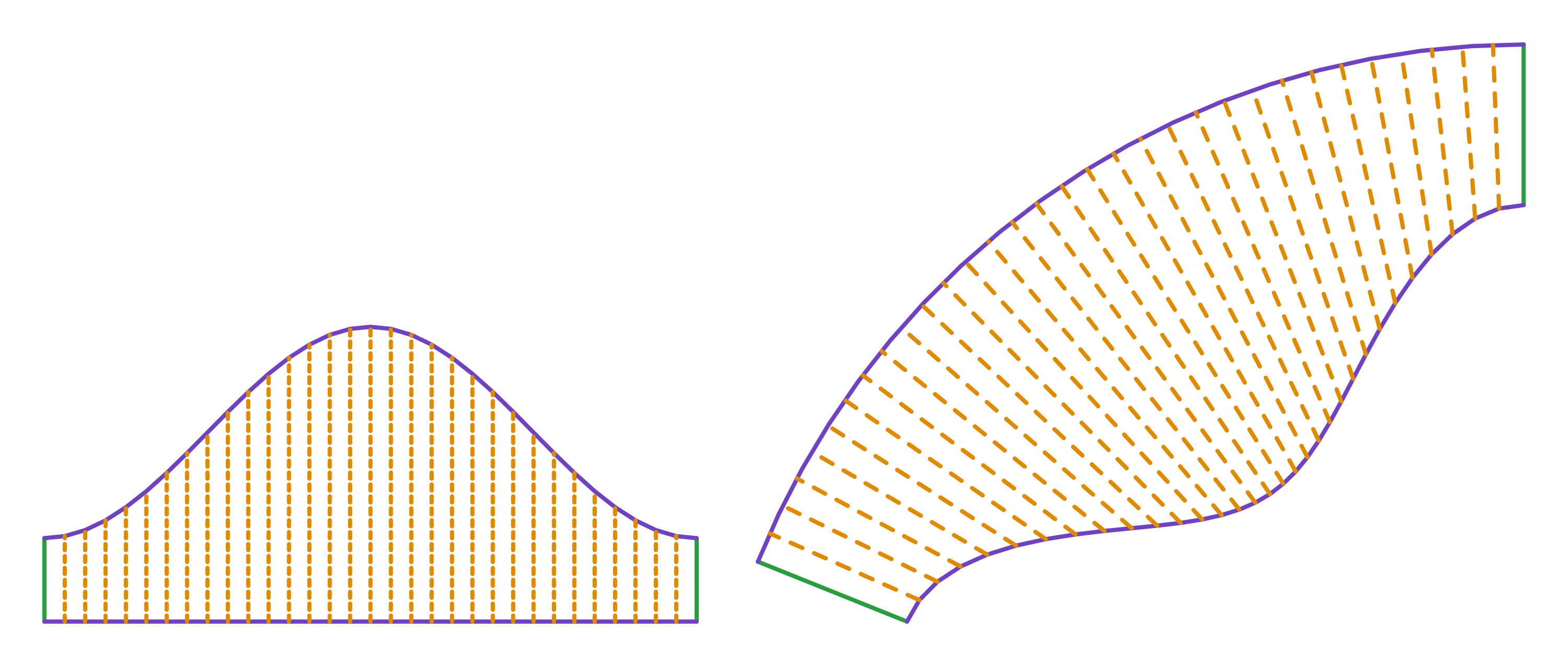
shell: π × (D − t) ; sector: 360° × sin βThe shell is 1247.2 mm round and 159.6 to 563.9 mm high; the sector opens 360° × sin β = 68.1°, with generators of 307.3 to 711.6 mm between the joint and the outlet.
Worked example
The values the form comes pre-filled with, run through the tool itself:
| Pipe diameter | 400 mm |
|---|---|
| Cone outlet diameter (outside) | 600 mm |
| From the foot of the pipe to the crossing of the centrelines | 400 mm |
| From the crossing of the centrelines to the cone outlet (on the cone's centreline) | 500 mm |
| Bend angle (between the centrelines) | 90° |
| Divisions | 32 |
| Plate thickness | 3 mm |
| Measured | Outside (outer face to outer face) |
| The flat pattern fits a plate of | 1464 × 1104 mm |
| Flat patterns produced | 2 |
Result of the example
| Plate 1 | 1247 × 564 mm |
|---|---|
| Area and weight | 0.45 m² · ≈ 10.6 kg in 3 mm steel |
| Plate 2 | 1464 × 1104 mm |
| Area and weight | 0.81 m² · ≈ 19.2 kg in 3 mm steel |
| Arc radii | 1,578.1 mm |
| Sector angle | 68.1° |
Ordinate table
| # | Position on the plate | Element height |
|---|---|---|
| 1 | 0 mm | 159.6 mm |
| 2 | 39 mm | 163.5 mm |
| 3 | 78 mm | 175 mm |
| 4 | 116.9 mm | 193.7 mm |
| 5 | 155.9 mm | 218.8 mm |
| 6 | 194.9 mm | 249.5 mm |
| 7 | 233.9 mm | 284.4 mm |
| 8 | 272.8 mm | 322.3 mm |
| 9 | 311.8 mm | 361.8 mm |
| 10 | 350.8 mm | 401.2 mm |
| 11 | 389.8 mm | 439.1 mm |
| 12 | 428.7 mm | 474.1 mm |
| 13 | 467.7 mm | 504.7 mm |
| 14 | 506.7 mm | 529.8 mm |
| 15 | 545.7 mm | 548.5 mm |
| 16 | 584.6 mm | 560 mm |
| 17 | 623.6 mm | 563.9 mm |
| 18 | 662.6 mm | 560 mm |
| 19 | 701.6 mm | 548.5 mm |
| 20 | 740.5 mm | 529.8 mm |
| 21 | 779.5 mm | 504.7 mm |
| 22 | 818.5 mm | 474.1 mm |
| 23 | 857.5 mm | 439.1 mm |
| 24 | 896.4 mm | 401.2 mm |
| 25 | 935.4 mm | 361.8 mm |
| 26 | 974.4 mm | 322.3 mm |
| 27 | 1,013.4 mm | 284.4 mm |
| 28 | 1,052.3 mm | 249.5 mm |
| 29 | 1,091.3 mm | 218.8 mm |
| 30 | 1,130.3 mm | 193.7 mm |
| 31 | 1,169.3 mm | 175 mm |
| 32 | 1,208.2 mm | 163.5 mm |
| 33 | 1,247.2 mm | 159.6 mm |
Assembly notes
The cone comes out with a 21.8° apex angle, tangent to the same sphere as the pipe, and that is why the two meet in a flat joint. Fit the two plates with the seams on the inside of the bend and check that the joint closes with no gap all the way round before welding.
How to mark it out on the plate
- Enter the pipe, the cone outlet, the two distances from where the centrelines cross, the bend angle and the thickness.
- Cut the shell and the sector from the templates and roll each one, with the seam on the inside of the bend.
- Bring the two legs together at the joint, with the seams lined up on the inside, and check that it closes with no gap all the way round before welding.
- Check the dimensions: h from the foot of the pipe to the crossing of the centrelines, and l from the crossing to the cone outlet.
Common mistakes and tolerances
- Squashing the cone oval to match the pipe
- There is no need: with the cone tangent to the same sphere as the pipe, both legs meet in the same ellipse. Drawing the cone through the outlet and any other point leaves a gap and means deforming it.
- Measuring h and l from the joint
- Both dimensions run from where the centrelines cross. The joint is slanted and cuts each leg at a different height all the way round.
- Fitting one plate turned round
- Both seams go on the inside of the bend; turned half a turn, one leg does not match the other.
Frequently asked questions
- How can the joint be flat if one leg is a cone?
- Because both legs are tangent to the same sphere, with the pipe's radius, centred where the centrelines cross: two surfaces of revolution circumscribed about a common sphere meet in plane curves. The cone is the only one that touches the sphere and passes through the given outlet; in the example, it opens 21.81° at the apex. So there is no need to squash the cone oval to match the pipe.
- Where are h and l measured from?
- From where the centrelines cross: h runs down the pipe's centreline to its foot, and l along the cone's centreline to the outlet. It is the piping dimension, centre to face, and it does not depend on where the joint cuts each leg.
- Can the cone close instead of opening?
- It can: with the cone outlet smaller than the pipe, the bend turns and reduces. The apex moves beyond the outlet, and the joint stays flat.
- Where do the seams go?
- On the inside of the bend, on both plates, where the generators are shortest: 159.6 mm on the pipe and 307.3 mm on the cone, in the example, against 563.9 and 711.6 mm on the outside.
- What if both legs are cones?
- Then it is the tapered segmented bend with one gore: both half gores are cones of the same taper, and the joint is flat too. With the same diameter on both legs, it is the ordinary elbow.
You can work out the figures right here, with no account. PDF, DXF, 3D and history take an account — free, with unlimited calculations.