Rectangular Tap on Pipe flat pattern
What it is
The rectangular-section collar seated on a shell — the mouth where a rectangular duct enters a round pipe. The catalogue had the round branch on a pipe and the rectangular tube cut by a plane, and did not have the rectangular branch cut by the PIPE.
Where it is used
Intake and grille mouths on pipework, rectangular duct entries into a round header, chutes discharging into a pipe, suction take-offs.
Measurements the calculation needs
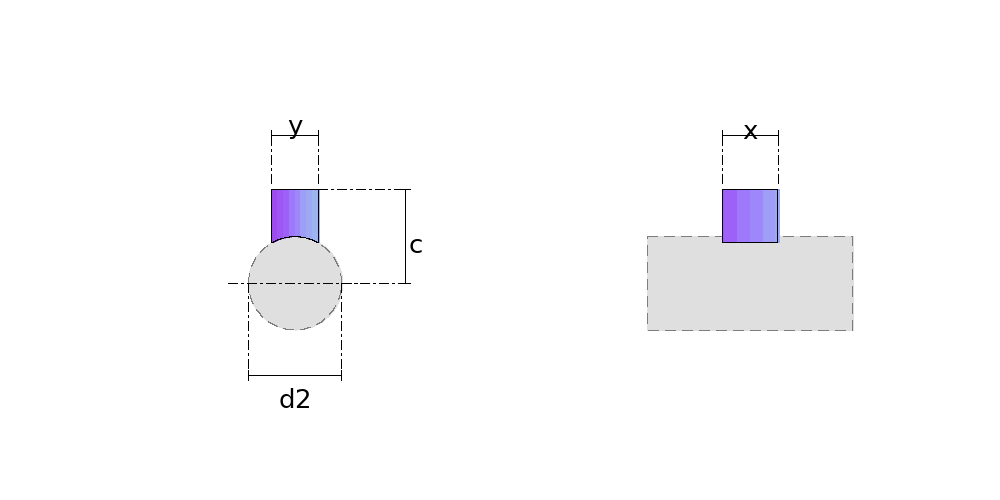
- D2 Outside diameter of the pipe
- X Side of the collar along the pipe
- Y Side of the collar across the pipe
- C Length, from the pipe axis to the top face
- DV Divisions
- THK Plate thickness
- R Bend radius
Calculate with your own measurements
No account needed: enter the measurements in millimetres or inches and get the figures and the drawing. The scaled PDF template, the DXF for the cutting table and the 3D model take a free account.
Diameters and sides are outside measurements. The flat pattern already allows for the plate thickness, working on the mean line.
Units: mm inches
Worked example
The values the form comes pre-filled with, run through the tool itself:
| Outside diameter of the pipe | 19-11/16" (19.685) |
|---|---|
| Side of the collar along the pipe | 11-13/16" (11.811) |
| Side of the collar across the pipe | 9-13/16" (9.8425) |
| Length, from the pipe axis to the top face | 19-11/16" (19.685) |
| Divisions | 16 |
| Plate thickness | 1/8" (0.1181) |
| Bend radius | 0" |
| The flat pattern fits a plate of | 42-13/16" × 11-1/8" |
Result of the example
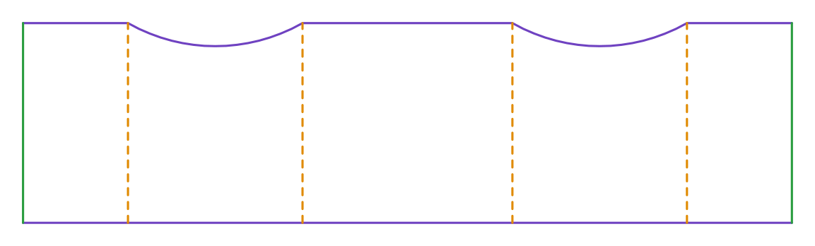
| Plate | 42-13/16" × 11-1/8" |
|---|---|
| Area and weight | 3.2 ft² · ≈ 15.4 lb in 1/8" steel |
Assembly notes
The pattern develops the SHARP CORNER, on the mean line — the theoretical layout, which is what gets delivered. If you fold it on a press brake with an inside radius, the blank comes out LONG: each fold needs, against this pattern, the deduction 2*(r+t/2)*tan(a/2) − a*(r + k*t), with r the inside radius, a the bend angle in radians, and your tooling's k. On a 500x300 tube in 1.5 mm sheet with four 90° folds that is 3.6 mm at radius 0.75 and 9.3 mm at radius 4.5 — always to be taken off. A welded or V-notched corner closes on the sharp corner and needs no deduction.
Fold to an angle of 90° BETWEEN THE TWO FACES — what a protractor reads on the finished part, not the press stroke angle. Every crease on this part has the same angle.
Frequently asked questions
- Are all four walls cut the same?
- No, and each pair is cut differently. The two perpendicular to the pipe's axis lie in planes that cut the cylinder in the CIRCLE ITSELF — the bite there is an arc of exact radius. The two parallel to the axis lie in planes that cut the cylinder in STRAIGHT LINES — the bite there is horizontal, the same end to end.
- Why only four fold lines?
- Because all four walls are flat. A station in the middle of an arc is a marking point, not a fold — only the collar's four corners bend. On a rolled part it is the other way round, which is why the round branch has one fold per station.
- And the hole in the shell, is it x by y?
- No, and that is the costliest mistake on this part. The hole is a rectangle, yes, but the side that runs across measures the ARC that y occupies on the shell: 2·Rn·asin(y/d2). On a 500 pipe with a 250-wide tap that is 260.2, not 250. Cut it x by y and the hole is narrow and the collar will not go in. The companion part in this catalogue draws the hole already corrected.
- Where do I measure the collar length from?
- From the AXIS of the pipe to the top face — the centre-to-face dimension, the same convention as the pipe branch. The deepest bite is the radius itself, so the length has to exceed it.
You can work out the figures right here, with no account. PDF, DXF, 3D and history take an account — free, with unlimited calculations.