How to lay out a fan scroll housing
What it is
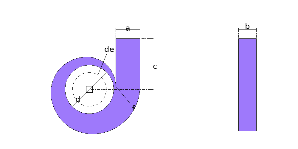
The scroll, or volute, is the spiral casing of a centrifugal fan or blower: it collects the air leaving the impeller and leads it to the outlet. It comes out of four plates -- the two side plates, the front one with the inlet hole, the band that wraps round the impeller and the cutoff plate, the inner wall of the outlet. The page lays out the spiral by the four-centre method, from the impeller, the cutoff clearance and the outlet, and gives the plates as DXF and as a 1:1 template.
Where it is used
Kitchen and paint booth extractors, forge and furnace blowers, woodworking dust collectors and chip extractors, and dryer and greenhouse fans.
Measurements the calculation needs
- D Impeller diameter
- F Cutoff clearance (impeller to cutoff)
- A Outlet opening
- B Inside casing width
- C Outlet height from the impeller axis
- DE Inlet diameter (0 = no hole)
- THK Plate thickness
Calculate with your own measurements
No account needed: enter the measurements in millimetres or inches and get the figures and the drawing. The scaled PDF template, the DXF for the cutting table and the 3D model take a free account.
Diameters and sides are outside measurements. The flat pattern already allows for the plate thickness, working on the mean line.
Inches or millimetres? mm inches
How it develops: the formulas
- Square and radii
s = A / 4 ; R1 = s/2 + √((d/2 + f)² − (s/2)²) ; Rk = R1 + (k − 1) × sThe four centres at the corners of a square of side s around the axis. In the example, s = 50 and R1 = 243.6 mm: the cutoff sits 220 mm from the axis, 20 of clearance.- Outlet
outlet = R4 − R1 + s = AThe cutoff and the end of the spiral sit at the same height, and the outlet walls rise square: 200 mm in the example.- Band
L = Σ π/2 × (Rk + t/2) + (c − s/2)On the mean line, the spiral and the straight outlet wall: 2402.9 mm in the example.- Side plates
outer radius = Rk + t ; cutoff outside face at x = R1 − s/2 − tOutside the band and the cutoff plate; the cutoff's outside face meets the first arc 2 × √(R1 × t) above the tip.
Worked example
The values the form comes pre-filled with, run through the tool itself:
| Impeller diameter | 400 mm |
|---|---|
| Cutoff clearance (impeller to cutoff) | 20 mm |
| Outlet opening | 200 mm |
| Inside casing width | 150 mm |
| Outlet height from the impeller axis | 420 mm |
| Inlet diameter (0 = no hole) | 280 mm |
| Plate thickness | 2 mm |
| The flat pattern fits a plate of | 2403 × 791 mm |
| Flat patterns produced | 4 |
Result of the example
| Plate 1 | 741 × 791 mm |
|---|---|
| Area and weight | 0.35 m² · ≈ 5.6 kg in 2 mm steel |
| Arc radii | 140 mm · 245.6 mm · 295.6 mm · 345.6 mm · 395.6 mm |
| Sector angle | 360 · 79.6 · 90° |
| Plate 2 | 741 × 791 mm |
| Area and weight | 0.42 m² · ≈ 6.5 kg in 2 mm steel |
| Arc radii | 245.6 mm · 295.6 mm · 345.6 mm · 395.6 mm |
| Sector angle | 79.6 · 90° |
| Plate 3 | 2403 × 150 mm |
| Area and weight | 0.36 m² · ≈ 5.7 kg in 2 mm steel |
| Plate 4 | 395 × 150 mm |
| Area and weight | 0.059 m² · ≈ 0.93 kg in 2 mm steel |

Assembly notes
Roll the band in four stretches, marked on the plate from the tip of the cutoff, each at its own radius on the inside face: 243.6, 293.6, 343.6 and 393.6 mm, over 384.2, 462.7, 541.3 and 619.8 mm of plate; the rest, 395 mm, stays straight as the outer wall of the outlet. The four centres are the corners of a 50 mm square around the impeller axis.
The side plates cover the band and the cutoff plate from outside: the band fits between them, 150 mm wide, with the cutoff 20 mm from the impeller and an outlet of 200 × 150 mm. The front plate carries the inlet hole; drill the back one for the motor shaft.
How to mark it out on the plate
- Enter the impeller diameter, the cutoff clearance, the outlet, the casing width, the outlet height from the axis, the inlet and the thickness.
- Cut both side plates, the front one with the inlet hole, the band and the cutoff plate, or send the DXF for cutting.
- Roll the band stretch by stretch, each at its own radius, starting from the tip of the cutoff, and leave the last stretch straight.
- Weld the band and the cutoff plate to one side plate along the outline, with the cutoff tip against the start of the band.
- Close with the other side plate, check the impeller clearance at the cutoff and drill the back plate for the motor shaft.
Common mistakes and tolerances
- Starting the spiral far from the impeller
- The cutoff clearance is what the fan feels most: with a wide gap, part of the air goes round and never leaves. Keep it between 5% and 10% of the impeller diameter.
- Rolling the band at a single radius
- The scroll grows: each quarter has its own radius, one side of the square larger than the last. At a single radius the outlet comes out crooked and small.
- Measuring the spiral on the outside
- The layout dimensions are on the inside face, the one the air runs along; the band develops on the mean line and the side plates go one thickness beyond. Measured outside, the clearance and the outlet shrink by a thickness.
Frequently asked questions
- How do you lay out a fan scroll?
- By the four-centre method: a square whose side is a quarter of the outlet, centred on the impeller axis, and the spiral in four quarter circles, each struck from one corner of the square with a radius one side larger than the last. In the example, a 200 outlet gives a 50 mm square and radii of 243.6, 293.6, 343.6 and 393.6 mm on the inside face.
- What clearance between the impeller and the cutoff?
- 5% to 10% of the impeller diameter, the rule in fan design books: less and the cutoff whistles, more and part of the air goes round again. In the example, 20 mm on a 400 impeller. The spiral starts at that point, the closest to the impeller.
- How long is the band?
- The spiral on the mean line plus the straight outer wall of the outlet: in the example, 384.2 + 462.7 + 541.3 + 619.8 = 2007.9 mm of spiral and 395 of straight, 2402.9 mm, by the casing width, 150. The plate comes with the radius changes marked, to roll each stretch at its radius.
- Why does the outlet come out the right size?
- Because the four-centre spiral grows by exactly the outlet in one turn: the cutoff and the end of the spiral sit at the same height, one outlet apart, and both outlet walls rise square, tangent to it. In the example, 200 × 150 mm.
- Do the side plates cover the band?
- Yes: their outline is the outside face of the band and of the cutoff plate, one thickness beyond the spiral, and the band fits between them at the casing width. The front one carries the inlet hole; the back one comes out whole, for whatever shaft hole the motor needs.
You can work out the figures right here, with no account. PDF, DXF, 3D and history take an account — free, with unlimited calculations.