Pipe on a Bend (Dummy Leg) flat pattern
What it is
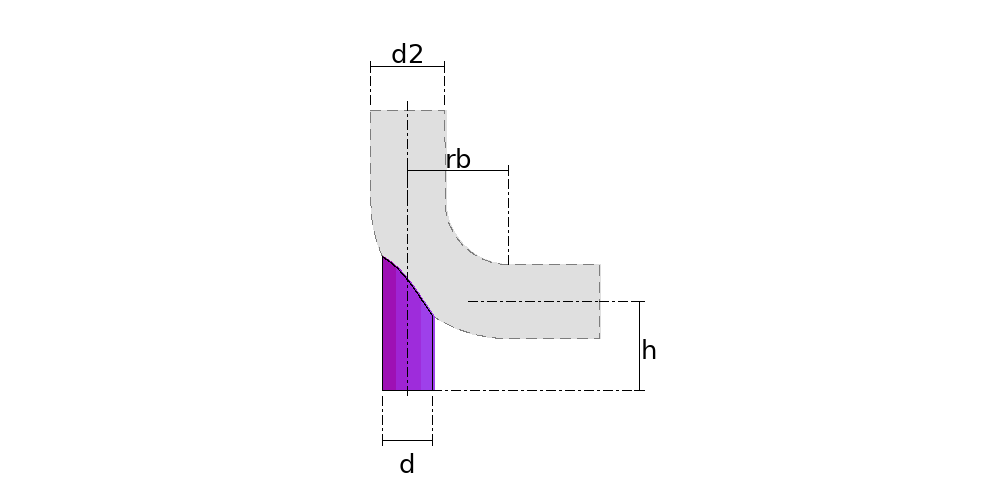
The pipe on a bend is the support cut to sit on the back of a 90° bend: the dummy leg of process piping, which carries the centreline of the vertical leg down through the bend to the support, and the trunnion. The bend is a torus, so the mouth is not that of a branch on a straight pipe: the back drops as the bend turns, and the mouth is deeper on the side of its centre.
Where it is used
Dummy legs and trunnions in refineries, power plants and chemical plants; supports for bends in steam, water and compressed-air lines; feet for chimneys and round ducts that turn; reinforcement for pneumatic conveying bends.
Measurements the calculation needs
- D2 Bend diameter
- RB Bend radius (on the centreline)
- D Support diameter
- E Offset of the support's centreline from the vertical leg's (towards the bend's centre)
- H Height from the horizontal leg's centreline to the foot of the support
- DV Divisions
- THK Plate thickness
- REF Measured
Calculate with your own measurements
No account needed: enter the measurements in millimetres or inches and get the figures and the drawing. The scaled PDF template, the DXF for the cutting table and the 3D model take a free account.
Diameters and sides outside to outside, inside or on the mean line, as set in “Measured”. The pattern already takes off the thickness, on the mean line.
Units: mm inches
How it develops: the formulas
The worked figures on this page are for the metric example: D2 168.3 mm · RB 228.6 mm · D 114.3 mm · E 0 mm · H 200 mm · DV 16 · THK 6 mm. In inches the example and the calculator start from those sizes rounded to the tape, so their numbers differ slightly.
- Where it meets the back
z = −√((rb + √(R² − x²))² − (y − rb)²)Each generator of the support is a vertical line, x from the plane of the bend and y from the centreline of the vertical leg; R is the outside radius of the bend and rb its centreline radius. The torus cut at x from the plane of the bend is two circles of radii rb ± √(R² − x²), and the generator meets the outer one. Past y = rb it is under the horizontal leg, and z = −rb − √(R² − x²).- Length of each generator
L(φ) = h + rb + z ; x = r × sin φ ; y = e + r × cos φr is the mid-line radius of the support, (d − thickness) / 2, and φ the angle from the side of the bend's centre. In the example, from 169.0 mm at the seam to 294.9 mm on the outside, on L = π × (d − thickness) = 340.2 mm.- The minimum height
h > the deepest drop of the mouth below the horizontal leg's centrelineIn the example, 31.0 mm: a shorter support would not reach the bend on the side of its centre.
Worked example
The values the form comes pre-filled with, run through the tool itself:
| Bend diameter | 6-1/2" |
|---|---|
| Bend radius (on the centreline) | 9" |
| Support diameter | 4-1/2" |
| Offset of the support's centreline from the vertical leg's (towards the bend's centre) | 0" |
| Height from the horizontal leg's centreline to the foot of the support | 8" |
| Divisions | 16 |
| Plate thickness | 1/4" |
| Measured | Outside (outer face to outer face) |
| The flat pattern fits a plate of | 13-3/8" × 11-7/8" |
Result of the example
| Plate | 13-3/8" × 11-7/8" |
|---|---|
| Area and weight | 0.89 ft² · ≈ 9.1 lb in 1/4" steel |
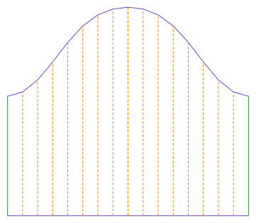
Ordinate table
| # | Position on the plate | Element height |
|---|---|---|
| 1 | 0" | 6-7/8" |
| 2 | 13/16" | 7-1/8" |
| 3 | 1-11/16" | 7-13/16" |
| 4 | 2-1/2" | 8-13/16" |
| 5 | 3-5/16" | 9-7/8" |
| 6 | 4-3/16" | 10-13/16" |
| 7 | 5" | 11-7/16" |
| 8 | 5-13/16" | 11-3/4" |
| 9 | 6-11/16" | 11-7/8" |
| 10 | 7-1/2" | 11-3/4" |
| 11 | 8-3/8" | 11-7/16" |
| 12 | 9-3/16" | 10-13/16" |
| 13 | 10" | 9-7/8" |
| 14 | 10-7/8" | 8-13/16" |
| 15 | 11-11/16" | 7-13/16" |
| 16 | 12-1/2" | 7-1/8" |
| 17 | 13-3/8" | 6-7/8" |
Assembly notes
The seam goes on the side of the bend's centre, on the shortest generator, 174.3 mm; the longest, 301.5 mm, is on the outside, in line with the vertical leg. Seat the mouth on the back with the support's centreline parallel to the vertical leg's and check that it touches all the way round before welding.
How to mark it out on the plate
- Enter the bend (outside diameter and centreline radius), the support diameter, the offset of its centreline from the vertical leg's, the height from the horizontal leg's centreline to the foot, and the thickness.
- Mark out a rectangle of L by the longest generator, divide L into dv parts and mark the height of each generator up from the foot, with the seam on both edges.
- Join the points with a flexible rule, cut and roll like a shell.
- Seat the mouth on the back with the support's centreline parallel to the vertical leg's and the long generator on the outside, and check that it touches all the way round before welding.
Common mistakes and tolerances
- Cutting the mouth as for a straight pipe
- A branch on a straight pipe sits on a cylinder; the bend is a torus, and its back drops as it turns. A straight-pipe mouth leaves a gap on the side of the bend's centre.
- Measuring the height from the start of the bend
- The height runs from the horizontal leg's centreline to the foot. Measured from anywhere else, the support comes out short or long by the difference.
- Fitting the support turned round
- The long generator is on the outside, in line with the vertical leg. Turned half a turn, the support does not seat.
Frequently asked questions
- Where is the height of the support measured from?
- From the centreline of the horizontal leg down to the foot of the support, which is the elevation of the line above the support. In the example, 200 mm: the mouth rises 94.9 mm above that centreline on the outside, where the support carries on the vertical leg, and drops 31.0 mm below it on the side of the bend's centre.
- What is the offset for?
- At zero the support continues the centreline of the vertical leg, the catalogue dummy leg. Moved towards the bend's centre it seats lower on the back; past the bend radius it is already under the horizontal leg. Outwards, the limit is the outer generator touching the start of the bend.
- Can the support be the same diameter as the line?
- It can. At the same diameter and zero offset, the outer face of the support continues that of the vertical leg, and the mouth runs from the start of the bend to the bottom of the back. Wider than the bend, no: the outer generators would pass beside it without meeting it.
- Where does the seam go?
- On the side of the bend's centre, on the shortest generator: 169.0 mm in the example, on a 340.2 mm wrap. The longest, 294.9 mm, is on the outside. Those are the two to check with the tape once it is cut.
- What if the bend is segmented?
- This part sits on a smooth bend, forged or rolled, with a centreline radius. On a segmented bend the support rests on straight gores, and if it falls entirely on one gore the mouth is that of a pipe branch, at the angle between the support and that gore.
You can work out the figures right here, with no account. PDF, DXF, 3D and history take an account — free, with unlimited calculations.