Toriconical cone development: the cone with a knuckle
What it is
A toriconical cone is a cone that does not end in a sharp corner at the large end: it turns through a knuckle, an arc of a torus, until it is plumb, and runs on as a straight flange, which is where the weld to the shell sits, away from the bend. It is the conical bottom of silos and tanks and the reducer of pressure vessels. The page gives the flanging blank the way shops lay it out: one sector, the cone exact and the knuckle and flange by the true length of the meridian, with both knuckle lines marked and the excess the flanging gathers.
Where it is used
Conical bottoms of silos, hoppers and tanks, pressure vessel and column reducers, transitions from a shell to a large nozzle, and reactor and digester bottoms.
Measurements the calculation needs
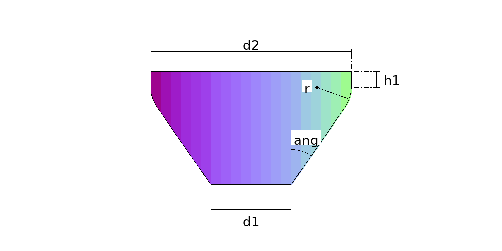
- D1 Small end outside diameter (d)
- D2 Large end outside diameter (D, the shell)
- R Inside knuckle radius (R)
- ANG Cone half angle (α, slant side to axis)
- H1 Straight flange (0 = none)
- THK Thickness
- CE Cone thickness rule
- NP Number of sheets
Calculate with your own measurements
No account needed: enter the measurements in millimetres or inches and get the figures and the drawing. The scaled PDF template, the DXF for the cutting table and the 3D model take a free account.
Diameters and sides are outside measurements. The flat pattern already allows for the plate thickness, working on the mean line.
Inches or millimetres? mm inches
How it develops: the formulas
- The knuckle centre and tangent line
c = D/2 − t − R ; rt = c + (R + t/2) × cos αOn the mean line. In the example, c = 397 mm and rt = 483.08 mm.- The sector radii
R2 = (d/2 − (t/2) × cos α) / sin α ; R1 = rt / sin α + (R + t/2) × α + flangeα in radians in the knuckle arc. In the example, 469.37 and 993.29 mm; with the thickness going to zero, the same example gives 471.77 and 995.72, the figures of the classic layout.- The sector angle
θ = 360° × sin αIn the example, 190.77°.- The knuckle marks
rt / sin α and rt / sin α + (R + t/2) × αThe two bend arcs: 911.60 and 968.29 mm in the example.- The excess at the edge
θ × R1 against π × (D − t)3307.2 against 3132.2 mm in the example: 5.59% that the flanging gathers.
Worked example
The values the form comes pre-filled with, run through the tool itself:
| Small end outside diameter (d) | 500 mm |
|---|---|
| Large end outside diameter (D, the shell) | 1000 mm |
| Inside knuckle radius (R) | 100 mm |
| Cone half angle (α, slant side to axis) | 32° |
| Straight flange (0 = none) | 25 mm |
| Thickness | 3 mm |
| Cone thickness rule | Along the normal (outside corner) |
| Number of sheets | One sheet (the whole piece) |
| The flat pattern fits a plate of | 1987 × 1087 mm |
Result of the example
| Plate | 1987 × 1087 mm |
|---|---|
| Area and weight | 1.28 m² · ≈ 30.0 kg in 3 mm steel |
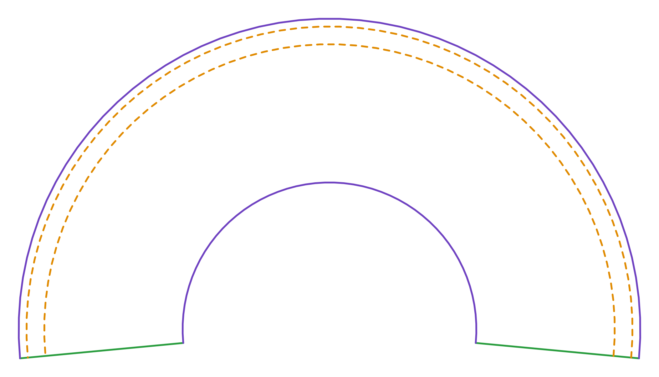
| Arc radii | 469.4 mm · 911.6 mm · 968.3 mm · 993.3 mm |
| Sector angle | 190.8° |
Assembly notes
Mark the two bend arcs on the plate. From the small end to the first one there are 442.2 mm of cone, rolled like any cone; between the two, 56.7 mm of plate become the knuckle, 100 mm inside radius; the last 25 mm are the straight flange, plumb. Finished, the part is 453.8 mm tall on the mean line, from the small end to the edge of the flange.
The plate carries the length of the knuckle and the flange, but not their circumference: the edge comes out 5.6% longer than the circumference of the finished part, and flanging gathers that excess, thickening the edge. Roll the cone, close the seam, and only then flange the marked band.
How to mark it out on the plate
- Enter D and d on the outside, the half angle, the inside knuckle radius, the straight flange and the thickness.
- Cut the sector, or send the DXF to the cutter, and mark the two bend arcs.
- Roll the cone and close the seam.
- Flange the band between the arcs until the flange is plumb, and check the flange diameter with a tape: π × D outside.
- Weld the flange to the shell.
Common mistakes and tolerances
- Taking the knuckle radius on the outside
- The code radius is the inside one. With the outside one in the field, the knuckle comes out one thickness wider and the tangent line moves.
- Laying out the cone to the corner
- Without the knuckle, a cone run out to D has the wrong slant length: in the example the outer arc would come out at 941.1 mm instead of 993.29, 52.2 mm short, and the part would not reach the shell.
- Being thrown by the edge excess
- The edge of the plate is longer than the finished circumference; checking it with a tape before flanging makes the sector look wrong. The note says how much is over.
Frequently asked questions
- How do you develop a toriconical cone?
- In one sector, like a cone: the angle is 360° × sin α, and the radius of each arc is the slant length of the mean line from the apex. The cone runs from the small-end arc to the tangent line with the knuckle, and from there the plate carries on by the length of the knuckle meridian, (R + t/2) × α, and the straight flange. In the example, the 190.77° sector has radii of 469.37 and 993.29 mm, with the knuckle marked between 911.60 and 968.29.
- Which dimensions do I enter?
- The diameters on the outside face, as for the cone: D is the shell the flange fits, d the small end. The knuckle radius is the inside one, as ASME and DIN give it, and α is the half angle, between the slant side and the axis. The straight flange runs from the tangent line with the knuckle to the edge.
- Why is the edge of the plate longer than the opening?
- Because the knuckle and the flange do not develop: the plate carries their length but not their circumference. In the example the edge is 3307.2 mm on the plate and 3132.2 on the finished part, on the mean line, 5.59% more; flanging gathers the excess and the edge thickens. The excess grows with the straight flange and with the knuckle radius.
- What knuckle radius should I use?
- ASME Section VIII, Division 1 asks for an inside knuckle radius on a toriconical head of at least 6% of the outside diameter and at least three times the thickness. The example uses 10%, like the Klöpper head: 100 mm on a D of 1000.
- What if the sector does not fit the plate?
- Choose how many plates, as for the cone: with 2 or 4, each part is the same sector divided, with the same radii and marks, and the parts are welded before flanging. In the example, in two halves, each fits in 1469 × 677 mm.
You can work out the figures right here, with no account. PDF, DXF, 3D and history take an account — free, with unlimited calculations.