Reinforcing Pad flat pattern
What it is
The reinforcing pad is the plate welded round a nozzle, outside the shell, to give back to the wall the metal the opening took out. It is rolled to the shell's outside diameter and bored to the nozzle's outside diameter, so the flat plate is not a round ring: it is the ring that, wrapped on the shell, sits round the nozzle. Around the shell it is wider than the pad diameter; along the shell it measures that diameter, or more with a sloping nozzle.
Where it is used
Nozzles and manways on pressure vessels, tanks, columns and heat exchangers; large-bore pipe branches, where the reinforcing collar replaces a forged fitting; openings in stacks and thin-wall ducting that need stiffness.
Measurements the calculation needs
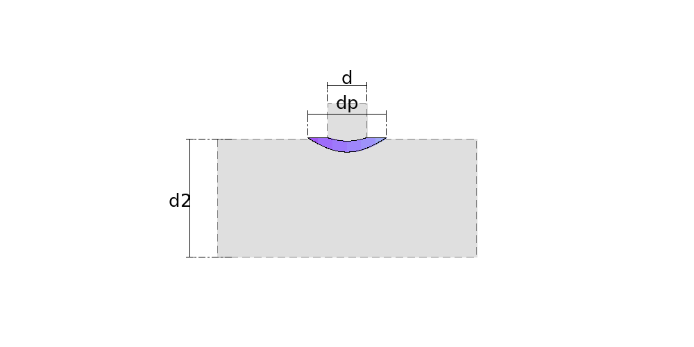
- D2 Shell outside diameter
- D Nozzle outside diameter (pad hole)
- DP Pad diameter (seen along the nozzle axis)
- ANG Angle between nozzle and shell axis
- DV Divisions
- THK Pad thickness
Calculate with your own measurements
No account needed: enter the measurements in millimetres or inches and get the figures and the drawing. The scaled PDF template, the DXF for the cutting table and the 3D model take a free account.
Diameters and sides are outside measurements. The flat pattern already allows for the plate thickness, working on the mean line.
Units: mm inches
How it develops: the formulas
The worked figures on this page are for the metric example: D2 600 mm · D 200 mm · DP 400 mm · ANG 90° · DV 32 · THK 8 mm. In inches the example and the calculator start from those sizes rounded to the tape, so their numbers differ slightly.
- Width around the shell
L = (D2 + t) × asin(Dp / D2)The arc the pad takes up on the shell, measured on its mean line. In the example (D2 = 600, Dp = 400, t = 8): L = 608 × asin(0.667) = 443.7 mm.- Length along the shell
C = Dp / sin(α)α is the angle between the nozzle and the shell axis. Square (α = 90°), C = Dp = 400 mm; at 60°, 461.9 mm.- The hole
around: (D2 + t) × asin(D / D2) ; along: D / sin(α)The same sums with the nozzle diameter. In the example, 206.6 by 200.0 mm.- Point by point, with a square nozzle
around = (D2 + t)/2 × asin(r × sin φ / R) ; along = r × cos φr is the circle radius (Dp/2 for the edge, D/2 for the hole), R = D2/2, and φ the angle round the nozzle axis. That is how the ring is marked out by hand, by coordinates from the centre.
Worked example
The values the form comes pre-filled with, run through the tool itself:
| Shell outside diameter | 24" |
|---|---|
| Nozzle outside diameter (pad hole) | 8" |
| Pad diameter (seen along the nozzle axis) | 16" |
| Angle between nozzle and shell axis | 90° |
| Divisions | 32 |
| Pad thickness | 5/16" |
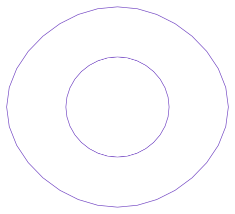
| The flat pattern fits a plate of | 17-3/4" × 16" |
Result of the example
| Plate | 17-3/4" × 16" |
|---|---|
| Area and weight | 1.1 ft² · ≈ 14.6 lb in 5/16" steel |
Assembly notes
Roll the pad to the outside diameter of the shell, 609.6 mm, before fitting it: it is developed on its own mean radius, outside the shell. Fit it with the hole round the nozzle and check that the edge bears on the shell all the way round. The tell-tale hole goes at the lowest point of the pad, after rolling.
How to mark it out on the plate
- Divide the pad circle and the hole circle into equal parts round the nozzle axis, and work out for each point the distance around and the distance along the shell.
- Draw two lines on the plate through the centre — around and along the shell — and mark each point by its two distances; join the edge points and the hole points.
- Cut, roll to the shell's outside diameter and check the pad in place: the edge must bear on the shell all the way round.
Common mistakes and tolerances
- Cutting a round ring, Dp by D
- Wrapped on the shell it comes out narrow around it and the edge stands off. In the example the plate must measure 443.7 mm around and 400 along, not 400 both ways.
- Developing on the shell's inside diameter
- The pad sits outside the shell, and its plate wraps on the shell's outside diameter plus its own thickness. Developed on the inside, the pad comes out short around.
Frequently asked questions
- What diameter and thickness should the pad be?
- The design's: the pad replaces the area of the opening, and the reinforcement calculation of the equipment code (in ASME VIII, the area replacement of UG-37) says how much. Planichapa does not size the reinforcement; it develops the pad the design calls for. In practice the diameter is often close to twice the opening and the thickness the same as the shell.
- Where is the pad diameter measured?
- From above, along the nozzle axis, as the vessel data sheet gives it. That diameter does not appear anywhere on the flat plate: along the shell the pad measures Dp / sin(angle), and around it, the arc Dp takes up on the shell — 443.7 mm in the example, for a 400 pad on a 600 shell.
- Is the pad hole the nozzle outside diameter?
- Yes: the pad wraps the nozzle from outside. The gap and the weld bevel between the two are up to whoever preps the joint; to have the gap on the template, add it to the nozzle diameter before calculating.
- What is the tell-tale hole for?
- It is a small threaded hole in the pad (1/4" is usual) for testing the pad welds with air and soap before the vessel's hydrotest. It stays open in service to show if the weld leaks. Drill it at the lowest point of the pad, after rolling.
- Does it work with a sloping nozzle, or on a head or cone?
- Sloping, yes: from 30° to 90° between the nozzle and the shell axis, and the pad stretches along the shell. On heads and cones, not yet: only on a cylindrical shell.
You can work out the figures right here, with no account. PDF, DXF, 3D and history take an account — free, with unlimited calculations.